Valve Assemblies for Clutch Systems

A technology of valve components and clutches, applied in the field of clutch systems, which can solve the problems of valves no longer closing safely and completely, disturbing noise development, unclear internal leakage of active cylinders, etc.

Active Publication Date: 2017-11-24
SCHAEFFLER TECH AG & CO KG
View PDF7 Cites 0 Cited by
  • Summary
  • Abstract
  • Description
  • Claims
  • Application Information

AI Technical Summary

Problems solved by technology

[0004] A disadvantage of the solutions known from the prior art for connecting hydraulic components in clutch systems is that the compensating suction valve may have the property that it filters possible Dirt particles that subsequently cause valve failure
This can lead, for example, to the fact that the valve is no longer securely and completely closed and therefore the master cylinder may have undefined internal leaks
Furthermore, such valve assemblies often have disturbing noise development

Method used


Image

  • Valve Assemblies for Clutch Systems
  • Valve Assemblies for Clutch Systems
  • Valve Assemblies for Clutch Systems

Examples


Embodiment Construction

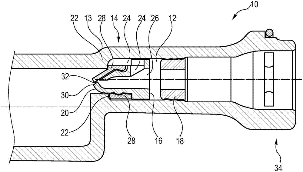
[0036] exist figure 1 Valve assembly 10 is shown in . The valve assembly 10 can be used in particular in hydraulically actuatable clutch systems, such as in particular engaging or disengaging systems. In this case, the valve assembly 10 can be arranged in a freely selectable area of ​​the clutch system, for example in the high-pressure area of ​​the engaging or disengaging system, lines, torque limiters (PTL), adapters, shock absorbers, clutch slaves, etc. Moving parts such as CSC or other components.

[0037] The valve assembly 10 comprises a channel 12 for the pressure-tight conduction of hydraulic fluid. A valve body 14 is arranged in the channel 12 . according to figure 1 , the channel 12 is delimited by a housing 13 which is an integral part of the master cylinder. Here, the circumference of the valve body 14 is expediently matched at least partially in shape and size to the inner circumference of the housing 13 or to the geometry of the channel 14 , so that a sealin...


PUM


Abstract

The present invention relates to a valve assembly for a hydraulically actuatable clutch system, comprising a channel for conducting a hydraulic fluid in a pressure-tight manner, wherein a valve body is arranged in the channel, wherein a slave-side sealing seat is provided adjacent to a slave-side end of the valve body, wherein a master-side sealing seat is provided adjacent to a master-side end of the valve body, and wherein the valve body is arranged in such a way that the valve body can be moved between a position in which the valve body is in contact with the slave-side sealing seat and a position in which the valve body is in contact with the master-side sealing seat, wherein the valve body has a first guide for conducting hydraulic fluid, which first guide is closed in a position of the valve body in which the valve body is in contact with the master-side sealing seat and is open in a position of the valve body in which the valve body is in contact with the slave-side sealing seat, and wherein the valve body has a second guide for conducting hydraulic fluid, which second guide can be closed by a sealing element, wherein the sealing element automatically closes the second guide when there is a master-side overpressure and automatically opens the second guide when there is a slave-side overpressure. A valve assembly described above makes it possible in particular to create a hydraulically actuatable clutch system that can operate especially comfortably, reliably, and stably over a long period.

Description

technical field [0001] The invention relates to a hydraulically actuatable clutch system and in particular to an engaging or disengaging system of a clutch. In particular, the invention relates to a valve arrangement according to the features of claim 1 for a hydraulically actuatable clutch system having, for example, a double clutch. Background technique [0002] A hydraulic system comprising a master cylinder, a slave cylinder and the pressure medium line connecting them is used, for example, in a clutch system for actuating a vehicle clutch in a drive train of a motor vehicle. A vehicle clutch is used to selectively interrupt torque transfer between an internal combustion engine and a shift transmission. [0003] In this case, valve assemblies are usually used in the pressure medium line in order to avoid underpressure at the slave cylinder. For example, such valve assemblies on master cylinders can have compensating suction valves. [0004] A disadvantage of the solut...

Claims


Application Information

Patent Timeline
Patent Type & Authority Patents(China)
IPC IPC(8): F16D25/12
CPCF16D25/14F16D2121/02F16D25/12F16D48/02F16D2023/0693F16D2048/0221
Inventor T·拉姆霍费尔J·格拉本斯塔特尔
Owner SCHAEFFLER TECH AG & CO KG
Why Eureka
Try Eureka