Pull head for laying cables

A technology for laying cables and pulling heads, which is applied in the electrical field, can solve problems such as time-consuming, high manufacturing cost, and cumbersome cable connection process, and achieve the effects of simple structure, convenient installation, and avoiding damage

Active Publication Date: 2016-03-30
安徽国通电力建设有限公司
View PDF7 Cites 0 Cited by
  • Summary
  • Abstract
  • Description
  • Claims
  • Application Information

AI Technical Summary

Problems solved by technology

The disadvantage of the existing cable pulling head is that the process of connecting with the cable is cumbersome, time-consuming, and the manufacturing cost is high

Method used


Image

  • Pull head for laying cables
  • Pull head for laying cables

Examples


Embodiment Construction

[0012] The specific implementation manner of the present invention will be described below in conjunction with the accompanying drawings.

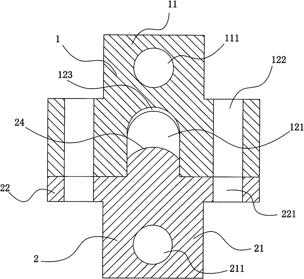
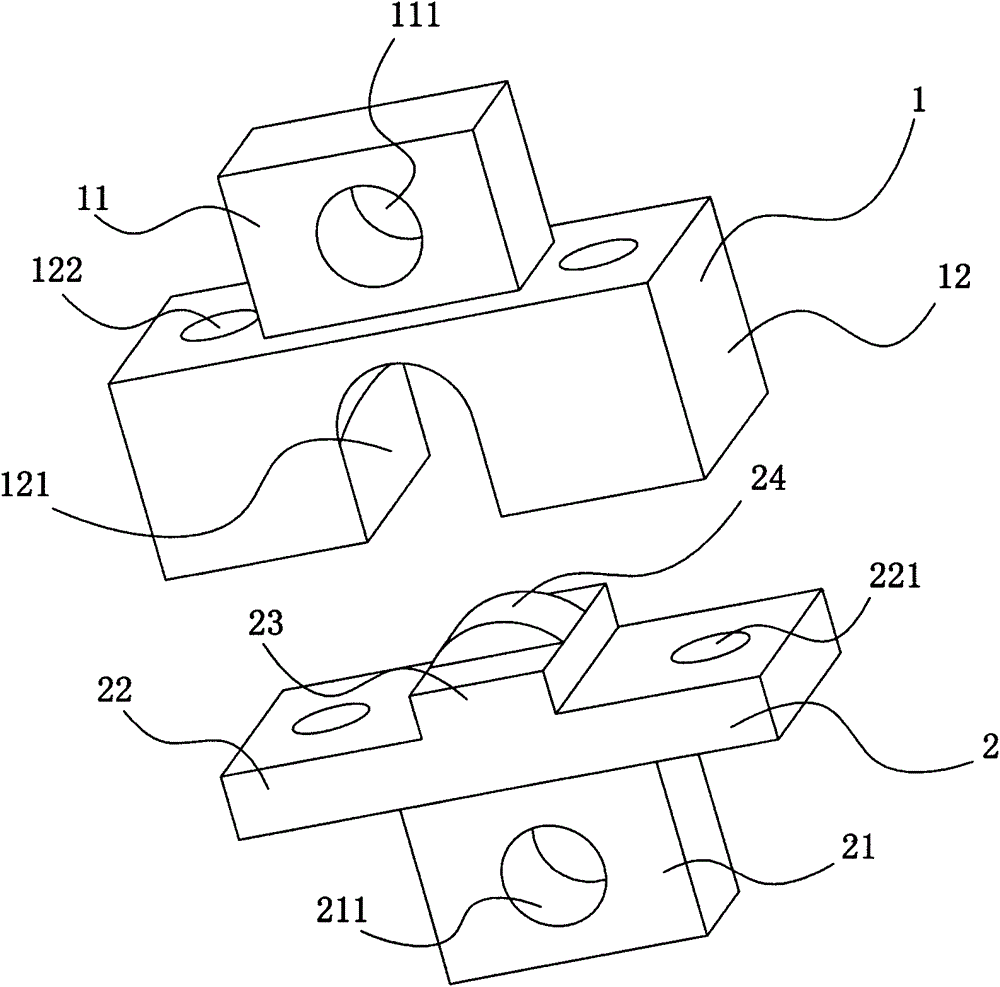
[0013] See figure 1 and figure 2 , the present invention comprises a base 2, the indenter 1 is affixed to the base 2, the base 2 is a T-shaped structure, and includes a horizontal plate 22 with first connecting holes 221 at both ends, and the middle part of the lower surface of the horizontal plate 22 is connected with a first The vertical plate 21 of the fixed through hole 211, the middle part of the upper surface of the horizontal plate 22 has a longitudinal flange 23, the upper surface of the longitudinal flange 23 has a transverse protrusion 24, and the upper surface of the transverse protrusion 24 is an arc-shaped structure; It includes a bottom block 12 with a U-shaped groove 121 matched with the longitudinal flange 23 in the middle. The arc portion of the U-shaped groove 121 has an inner concave portion 123. The second connecting...


PUM


Abstract

The invention relates to a traction head for laying a cable. The traction head comprises a base, a pressing head is fixedly connected to the base, the base is of a T-shaped structure and comprises a transverse plate with two ends provided with first connection holes, the middle of the lower surface of the transverse plate is connected with a vertical plate provided with a first fixing through hole, the upper surface of the transverse plate is provided with a longitudinal convex edge, and a transverse protrusion is arranged on the upper surface of the longitudinal convex edge. The pressing head comprises a bottom block, wherein the middle of the bottom block is provided with a U-shaped groove matched with the longitudinal convex edge, the two ends of the bottom block are provided with second connection holes corresponding to the first connection holes, and a top block provided with a second fixing through hole is fixedly connected to the upper surface of the bottom block. The traction head for laying the cable is simple in structure, arranged at the head portion of the cable, and facilitates traction when the cable is laid. Due to the fact that a structure that the cable is arranged by vertically matching the pressing head with the base is adopted, and the traction head for laying the cable is convenient to install. The U-shaped groove with the recessed portion is formed in the pressing head, pressure on the cable is reduced, and the connection strength of the cable and the traction head is ensured, damage to the head portion of the cable is avoided to the maximum extent.

Description

technical field [0001] The invention relates to the field of electrical technology, in particular to an auxiliary device for cable laying. Background technique [0002] The laying process of the cable includes the process of unwinding the cable from the roller frame and the process of forwarding the cable. The forward transport of the cable needs to be pulled by the front end. In order to avoid damage to the cable head, the cable cannot be pulled directly when pulling, but it needs to be pulled The cable head is installed on the pulling head. The disadvantage of the existing cable puller is that the process of connecting with the cable is cumbersome, time-consuming, and the manufacturing cost is high. Contents of the invention [0003] Aiming at the above-mentioned shortcomings in the existing cable transportation, the applicant provides a pulling head for laying cables, which has the characteristics of simple structure, convenient installation and low manufacturing cost....

Claims


Application Information

Patent Timeline
Patent Type & Authority Patents(China)
IPC IPC(8): H02G1/06
Inventor 阙其奇
Owner 安徽国通电力建设有限公司
Why Eureka
Try Eureka