Economical camera-support-and-movement track-and-dolly system providing high stability and precision to camera movement

a technology of camera support and movement, which is applied in the direction of machine supports, instruments, transportation and packaging, etc., can solve the problems of not recommending the use of two types of tracks together, noticeable bumping at the joints, and most dollies not being able to navigate the 10′ circle. , to achieve the effect of high stability, convenient use and economic construction

Inactive Publication Date: 2005-10-20
LONGLEY BRIAN
View PDF16 Cites 37 Cited by
  • Summary
  • Abstract
  • Description
  • Claims
  • Application Information

AI Technical Summary

Benefits of technology

[0015] The present invention contemplates a camera support and movement track and dolly system that, nonetheless to being economical of construction and easy to use, accords high stability, and precise spatial movement, to a mounted camera of any type.
[0016] The system of the invention so functions because a (1) very squat, and compact, camera dolly precisely stably rests upon, and follows along, a (2) modular track that is itself easily and accurately positioned and affixed over any terrain or structure with both high positional accuracy and stability. Both the (1) dolly and the (2) track so function not because of any special materials or tolerances of construction, but rather because of careful attention to simple rules of mechanics.
[0018] Furthermore, the (1) track is very accurately and stably spatially and angularly positioned so as to ultimately support any desired camera shot(s) by the optional use of such simple geometric aids as a straight edge, a carpenter's level, and / or a piece of string for setting any radius of curvature. The (1) track is modular in construction, with segments that join seamlessly and without any substantial irregularities in position, surface contour, or direction (in either azimuth or elevation).
[0019] Thus, in accordance with the present invention, when the (1) track is very accurately and stably positioned, and when the camera is fixedly mounted to the (2) camera dolly that rides precisely and smoothly upon this track, then the only parameters of camera motion remaining are camera velocity and, optionally, camera acceleration. In accordance with the present invention, the rolling friction between the (1) track and the (2) camera dolly—which is relatively lightweight—is low, and the camera dolly may quite readily be pushed or pulled along the track, or can be driven by a motor, or can even be accelerated in motion as by benefit of the impulse derived from a falling weight—all with but minimal force and difficulty.
[0020] Overall in accordance with the present invention it is generally possible for an amateur to control the both the complex motion and the stability of a camera in each of space, angular orientation and time—even as such camera may be used for motion picture or video shots that are prolonged in duration and / or extensive in space—with substantially the same results, and with potentially less effort, as is normally obtained by the use of a complex, heavy and expensive studio camera motion system.
[0021] The camera motion system of the present invention is durable, light weight, and easy to erect, disassemble, move and store. It is modular in construction, and extendable (or repairable) by addition (or substitution) of, most normally, added or different sections of straight and / or curved track. The system of the present invention is not limited to supporting the movement of motion picture and / or video cameras, nor cameras in general, but will alternatively serve to precisely move many things, including instrumentation packages and even a human adult, in space, in angular orientation, and in time. 1. A System for Moving a Camera in Space

Problems solved by technology

However, Matthews does not recommend that the two types of track be used together.
This can create a noticeable “bump” at the joint.
However, most dollies will not navigate the 10′ circle without the addition of a multi wheeled device such as the Matthews “Centipede”.
However, corrections cannot account for path deviations.
Although some have suggested that the “shaky cam” look is artistic, for most people it gets annoying after a short while.

Method used


Image

  • Economical camera-support-and-movement track-and-dolly system providing high stability and precision to camera movement
  • Economical camera-support-and-movement track-and-dolly system providing high stability and precision to camera movement
  • Economical camera-support-and-movement track-and-dolly system providing high stability and precision to camera movement

Examples


Embodiment Construction

[0053] The following description is of the best mode presently contemplated for the carrying out of the invention. This description is made for the purpose of illustrating the general principles of the invention, and is not to be taken in a limiting sense. The scope of the invention is best determined by reference to the appended claims.

[0054] Although specific embodiments of the invention will now be described with reference to the drawings, it should be understood that such embodiments are by way of example only and are merely illustrative of but a small number of the many possible specific embodiments to which the principles of the invention may be applied. Various changes and modifications obvious to one skilled in the art to which the invention pertains are deemed to be within the spirit, scope and contemplation of the invention as further defined in the appended claims.

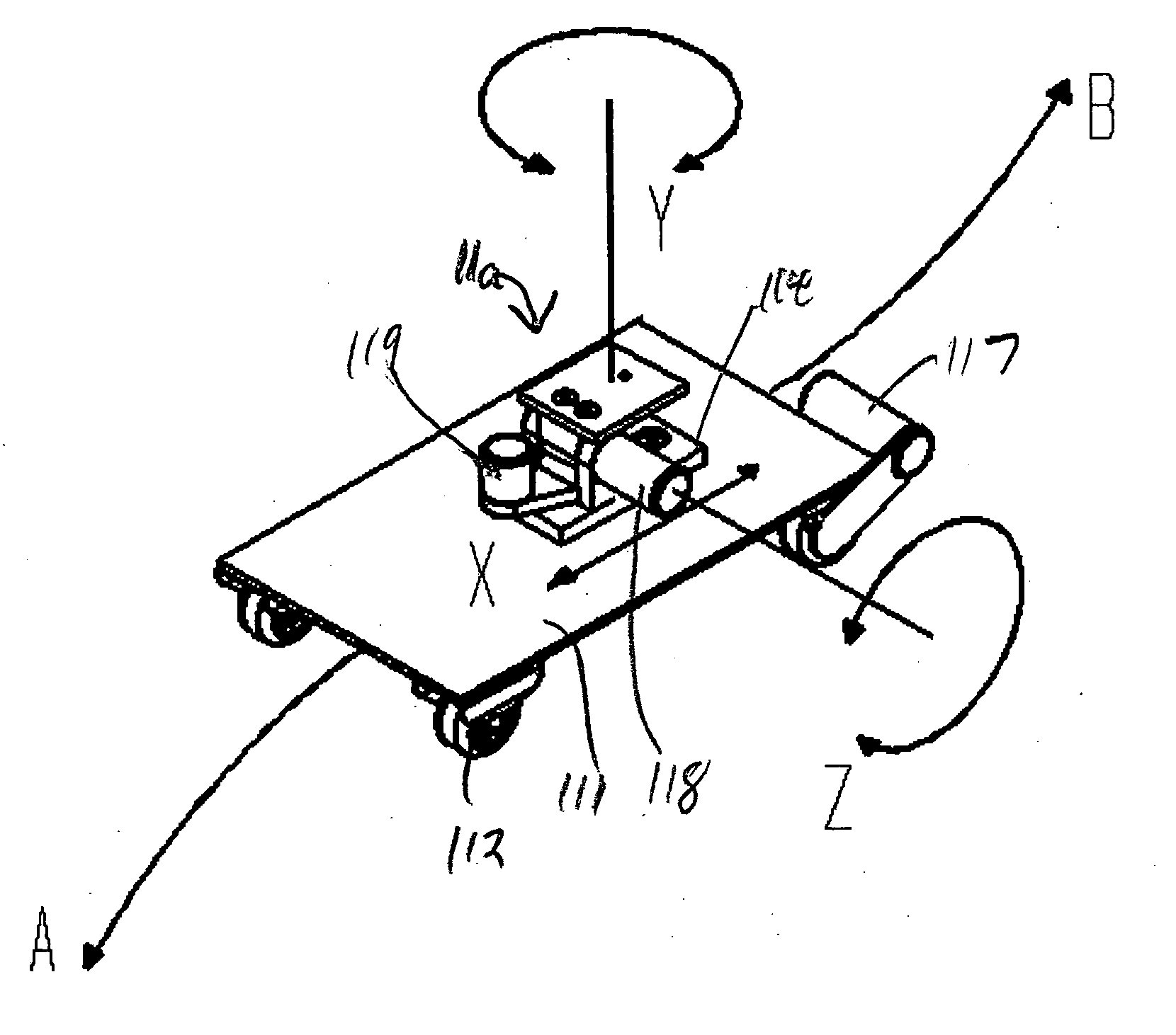
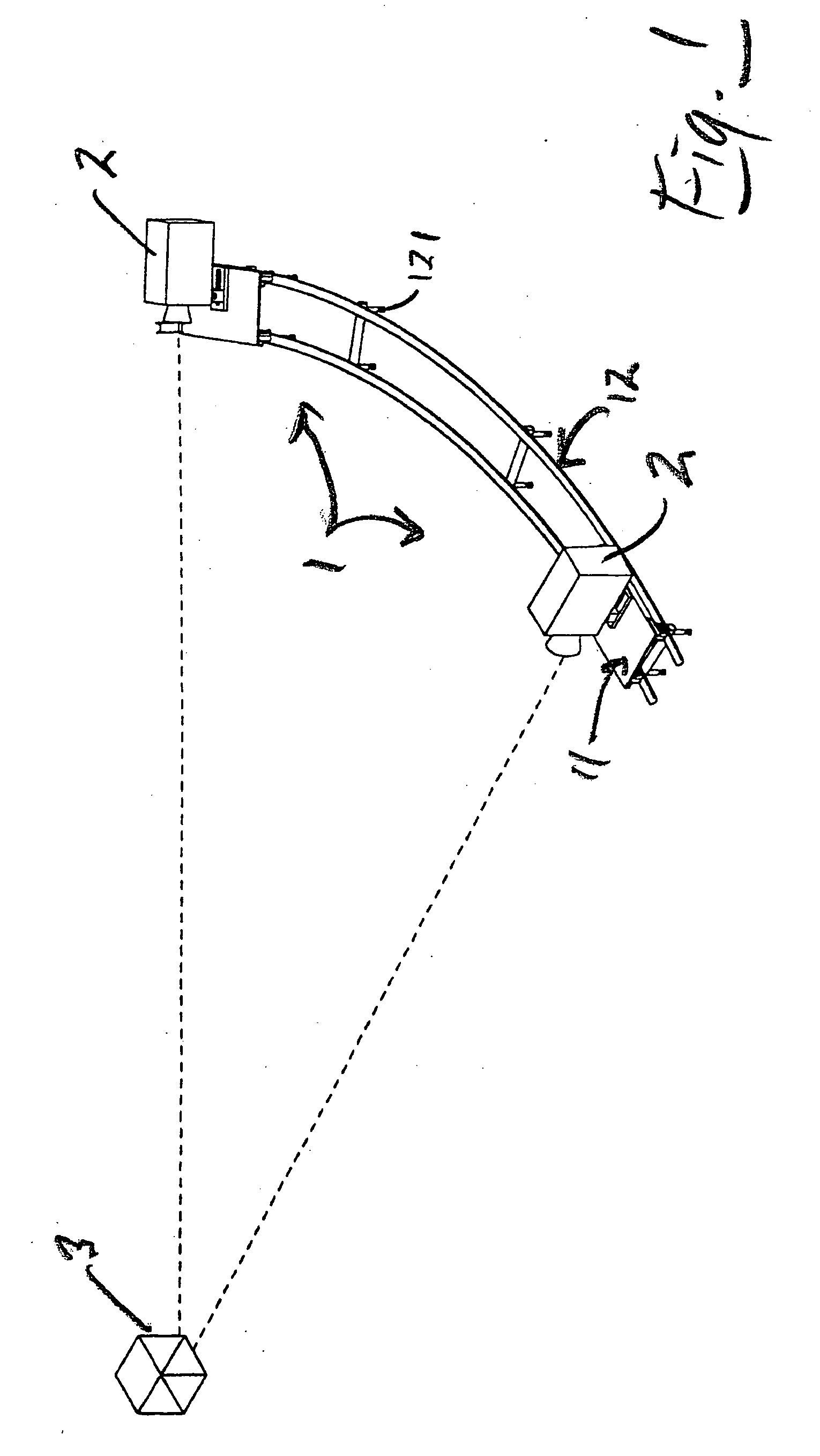
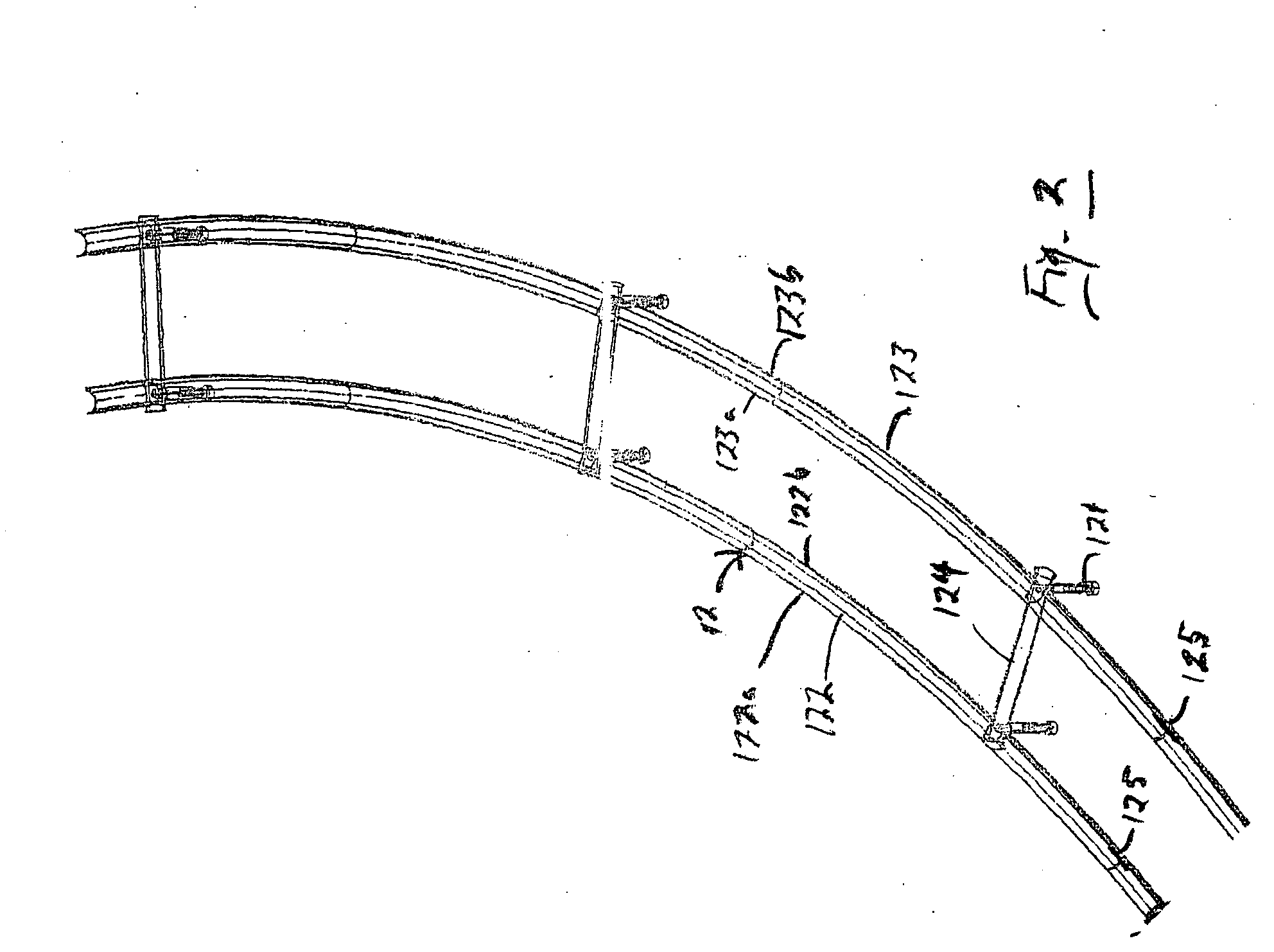
[0055] A preferred embodiment of a camera support and movement track and dolly system 1 in accordance with ...


PUM


Abstract

A system for moving a camera in space has a track with two spaced-parallel rails, each rail having two upward-extending spaced-parallel lips, and a dolly holding the camera and riding upon both rails of the track. The track is preferably segmented with each elongate rail segment preferably in the cross-section of half of a tube, while the dolly has wheels that contact only, and that ride upon, the upward-extending spaced-parallel lips of each half-tubular rail. The camera is mounted close upon the support platform of the generally rectangular wheeled dolly, which is itself squat and low to the track's two spaced-parallel rails. According to the geometries of construction, the camera is relatively insensitive in space and in angular orientation to such irregularities in track and moving dolly as are in any case minor by design, and the camera can be moved along complex paths with great precision for purposes of motion pictures and movies.

Description

BACKGROUND OF THE INVENTION [0001] 1. Field of the Invention [0002] The present invention generally concerns systems and methods for moving a camera in both space and angular orientation, as during the creation of motion pictures or videos [0003] The present invention particularly concerns construction of a track, and also a wheeled dolly that both rides upon the track and mounts a camera, so that both spatial and angular irregularities and errors both in the track and in the motion of the wheeled dolly are minor, and so that such irregularities and errors as are uneliminatable are not magnified in the spatial or angular orientation of the camera, which camera can be economically controlled to move with considerable stability and precision. [0004] 2. Description of the Prior Art [0005] The camera movement system of the present invention is related to camera car rigs, jib arms, dollies, dolly track, dolly spreaders, heads, tripods, and pedestals. [0006] These items of the prior art s...

Claims


Application Information

Patent Timeline
Patent Type & Authority Applications(United States)
IPC IPC(8): B62B3/00F16M11/42G03B21/00
CPCF16M11/42F16M11/08F16M11/425F16M11/2021F16M11/18
Inventor LONGLEY, BRIAN
Owner LONGLEY BRIAN
Why Eureka
Try Eureka