Vacuum hose storage system

a vacuum hose and storage system technology, applied in the field of vacuum hose storage systems, can solve the problems of occupying a large space, reducing the convenience of maintenance, and reducing the space needed for storage, so as to reduce production costs, prevent damage to the housing, and facilitate maintenan

Active Publication Date: 2011-02-24
H P PROD
View PDF31 Cites 35 Cited by
  • Summary
  • Abstract
  • Description
  • Claims
  • Application Information

AI Technical Summary

Benefits of technology

[0028]A further aspect of the present invention is to provide a U-shaped mounting bracket which is secured to the bottom wall of a storage cabinet or other mounting structure whereupon the housing can be snap-fitted therein to removably mount the housing on the storage bracket permitting easy removal for maintenance.
[0029]Still another feature of the present invention is to mold a plurality of stub shafts on opposed side walls of the housing to form roller shafts on which are rotatably mounted hose guide rollers within the internal storage compartment of the housing thereby reducing production costs by eliminating mounting separate shafts on the side walls for mounting the rollers thereon.
[0030]A still further aspect of the present invention is to form at least three holes in the spaced side walls of the housing, which holes receive standoff brackets formed on cardboard packing panels which space the housing from an outer packing box, which panels are then slidably received within the outer packing box to provide a gap or crush zone between the housing and the packing box preventing damage to the housing when shipped and stored.
[0031]Still another aspect of the invention is to provide various snap-fit grooves in the housing side walls enabling the housing side walls to be snap-fitted into and removed from the other portion of the housing enabling the internal mechanism of the housing to be readily accessible for servicing and maintenance procedures.

Problems solved by technology

In many situations, this is less convenient than desired since the homeowner must continually go to a remote location to retrieve the cleaning attachments and hose for use in a particular room and then return the cleaning attachment, cleaning wand and hose to the closet for final storage.
Also, these storage areas become cluttered and occupy needed space in other closets of the house.
However, the storage arrangement of this latter system requires the use of a power-driven mechanism for retracting the hose when not in use.
Although this may perform satisfactory for its intended purpose, it is a more costly installation than may be desired by many homeowners and it requires the hose to be dedicated to a single vacuum source.
Also, these units may tend to be weak because their size is very limited, and in addition, their dirt capacity may also be limited.
These types of cleanups usually are required in a kitchen, workroom or laundry area, but do not receive the homeowner's immediate attention due to the need of retrieving the relative long length of hose from the storage area and connecting it to a central vacuum system.

Method used


Image

  • Vacuum hose storage system
  • Vacuum hose storage system
  • Vacuum hose storage system

Examples


embodiment 100

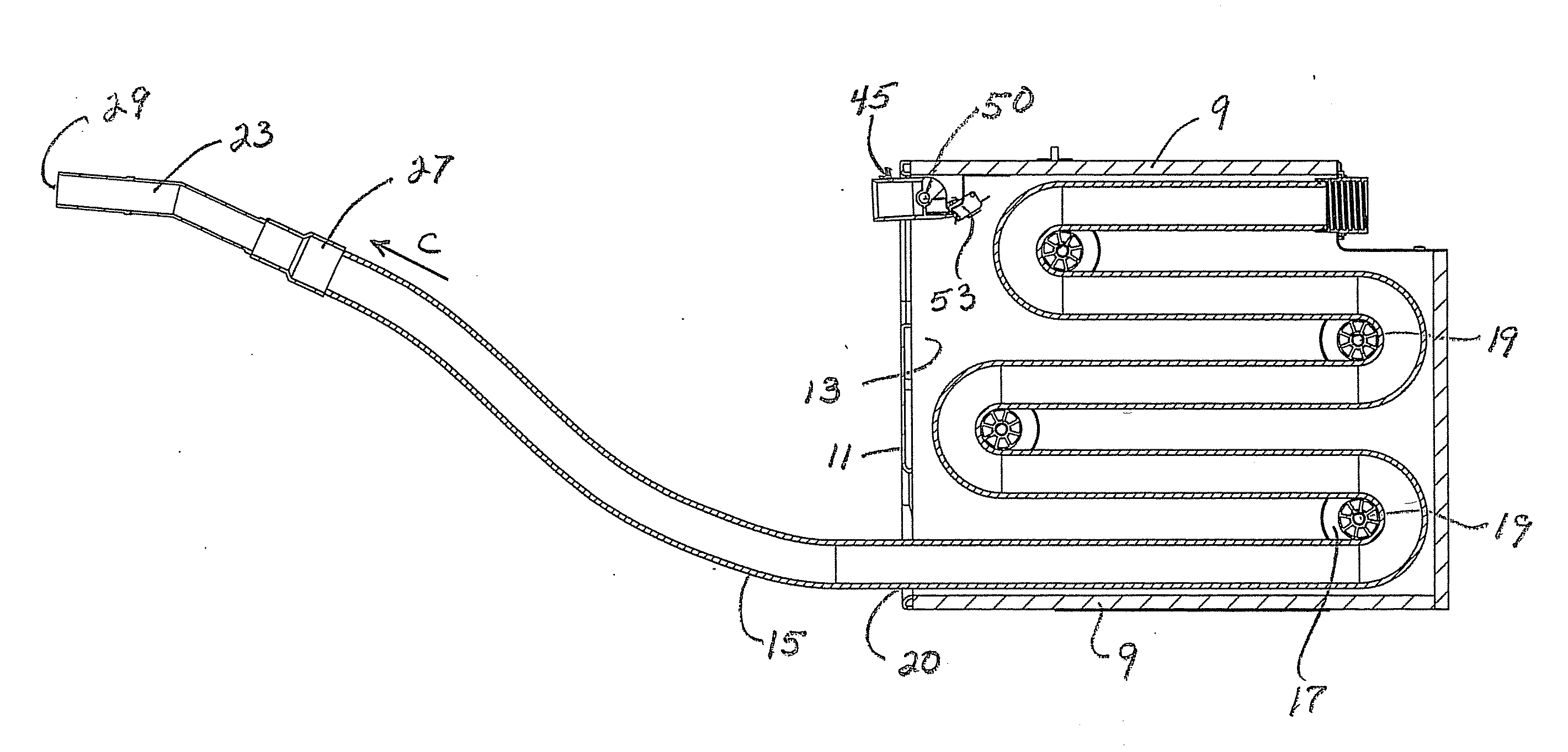
[0092]The main feature of embodiment 100 is the mounting of a length of rigid tubing indicated generally at 102, within housing interior 3 in a serpentine arrangement. Tubing 102 is fixedly mounted in the housing, and in the preferred embodiment will include five horizontally extending straight sections 104 connected by U-shaped bends or corners 106. Tubing 102 can be mounted by various types of attachment brackets (not shown) to the interior of the walls of housing 2 and terminates in an open end 108 which is adapted to be connected to a vacuum source, such as central vacuum unit 33 or to an adjacent self-contained vacuum motor 32 as shown in FIG. 15. The opposite open end 110 of tubing 102 communicates with front wall opening 20 of housing 2. Tubing 102 can be formed of various materials with the preferred type being a rigid ABS plastic tubing having a 2 inch outer diameter and a 1 ⅞ inch internal diameter. However, it is readily understood that the number of horizontal sections 1...

embodiment 1

[0094]Upon an operator removing handle 23 from cradle 45, it will either automatically start the vacuum source being applied to the interior of the hose by actuation of switch 53 or by a switch mounted on the handle (not shown). The operator pulls outwardly on the hose in the direction of arrow H (FIG. 20) to expand hose 115, as well as causing sliding seal 116 to move within the interior of tubing 102, moving from the position of FIG. 19 to that of FIG. 20. Upon further force being applied to handle 23, hose 115 will expand further, as well as sliding seal 116 extending further within the interior of tubing 102 to a fully extended position as shown in FIG. 21, in which position sliding seal 116 will engage a stop 118 attached to the open end 110 of tubing 102. This enables a greater length of hose to store within housing 2 and be available to the user than the construction wherein the inner hose end is firmly connected to the vacuum inlet tube, as in the embodiments shown above in ...

embodiment 200

[0098]In accordance with still another feature of embodiment 200, a one-way latch indicated generally at 216, is pivotally mounted on front wall 209 of housing 201 (FIGS. 26 and 27). Latch 216 preferably is formed as a stiff metal wire having a curved central section 218 and two free ends 220 which project into two openings formed in the housing adjacent side walls 205 and 207 to pivotally mount latch 216 thereon. Curved central section 218, when in a latched position with hose 15 as shown in FIG. 27, extends into one of the grooves or valleys 222 formed in hose 15 by internal helical spring 21 as shown in FIGS. 12 and 13. To use latch 216, a user will merely pivot the latch downwardly to the latched position of FIG. 27 wherein curved central section 218 becomes engaged within one of the hose grooves 222. This enables a user to merely pull the hose outwardly from its collapsed position toward the extended position which will automatically enable the hose to move past the downwardly ...


PUM


Abstract

A vacuum hose storage system includes a housing which is mounted in a storage area of a dwelling or vehicle and connected to a vacuum source. A length of flexible, expandable cleaning hose is mounted in a looped fashion about a plurality of spaced rollers rotatably mounted within the housing. A handle is attached to one end of the hose and is seated in a cradle formed in the housing when the hose is in a fully retracted position within the housing. The cradle is mounted in the housing and receives the open end of the hose when not in use and enables other vacuum tubes in the structure to be operational without shutting off the vacuum to the stored hose. An ON/OFF switch is located in the cradle for controlling the vacuum source and is actuated when the handle is placed in or removed from the cradle. The hose has an internal helical spring which biases the hose toward a retracted position about the spaced rollers within the housing. In an alternate embodiment, the hose is slidably extendable from within a rigid serpentine tubing mounting within the housing.

Description

CROSS REFERENCE TO RELATED APPLICATIONS[0001]This application is a continuation-in-part of U.S. patent application Ser. No. 12 / 341,571, filed Dec. 22, 2008, which is a continuation-in-part of U.S. patent application Ser. No. 12 / 151,174, filed May 5, 2008, which application claims priority from U.S. Provisional Patent Application Ser. No. 61 / 062,724, filed Jan. 29, 2008; the disclosures of which are incorporated herein by reference.BACKGROUND OF THE INVENTION[0002]1. Technical Field[0003]The invention relates to vacuum cleaning systems, and in particular to a storage system connected to a vacuum source for storing an extendable length of hose in a retracted condition within a storage housing. More particularly, the invention relates to a small, compact storage system adapted to be mounted in a concealed area within a home, such as in a kitchen cabinet, which contains a sufficient length of an expandable hose for ease of cleanup of the adjacent room.[0004]2. Background Information[000...

Claims


Application Information

Patent Timeline
Patent Type & Authority Applications(United States)
IPC IPC(8): A47L9/00
CPCA47L5/38A47L9/0009A47L9/0063Y10T137/6943
Inventor SMITH, JAMES F.GABRIC, ANDREW L.
Owner H P PROD
Why Eureka
Try Eureka