Abnormal wearing detection device for seal members and rotor device

a detection device and sealing technology, applied in the direction of fluid tightness measurement, instruments, machines/engines, etc., can solve the problems of unnecessari replacement, unusable measurement of temperature, and abnormal wear of oil seals which do not need to be replaced,

Active Publication Date: 2019-12-31
FANUC LTD
View PDF24 Cites 0 Cited by
  • Summary
  • Abstract
  • Description
  • Claims
  • Application Information

AI Technical Summary

Benefits of technology

[0007]Therefore, an object of the present invention is to provide an abnormal wearing detection device for seal members capable of detecting abnormal wearing of a seal member that slides in relation to a rotating member to seal the circumferential surface more reliably. Another object of the present invention is to provide a rotor device capable of detecting abnormal wearing of a seal member that slides in relation to a rotating member to realize a sealing function more reliably.
[0011]According to the present invention, it is possible to provide an abnormal wearing detection device for seal members capable of detecting abnormal wearing of a seal member that slides in relation to a rotating member to achieve a sealing function more reliably. According to the present invention, it is possible to provide a rotor device capable of detecting abnormal wearing of a seal member that slides in relation to a rotating member to realize a sealing function more reliably.

Problems solved by technology

However, in a method of measuring the temperature of the oil seal, it is not possible to determine whether the measured temperature is the temperature resulting from heating occurring due to abnormal wearing of the oil seal or the temperature transferred to the oil seal due to the heat of a stator.
Due to this, conventionally, there is a problem that an oil seal which does not need to be replaced is determined to be worn abnormally and is replaced unnecessarily.
Furthermore, since a rotor device is stopped when an oil seal is replaced, operations stagnate unnecessarily and operation efficiency may decrease.

Method used


Image

  • Abnormal wearing detection device for seal members and rotor device
  • Abnormal wearing detection device for seal members and rotor device
  • Abnormal wearing detection device for seal members and rotor device

Examples


Embodiment Construction

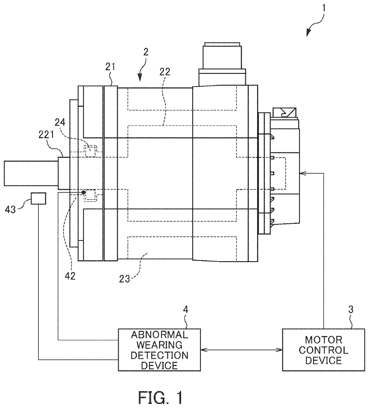
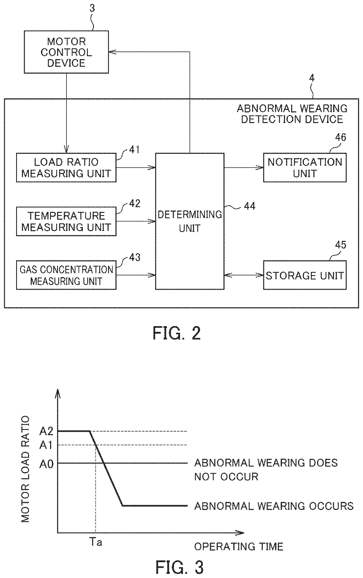
[0018]Hereinafter, an embodiment of the present invention will be described with reference to the drawings. FIG. 1 is a diagram for describing an embodiment of a rotor device having an abnormal wearing detection device for seal members according to the present invention. FIG. 2 is a block diagram for describing a configuration of an abnormal wearing detection device for seal members. In the present embodiment, a motor device 1 having a motor (an electric motor) 2 will be described as an example of a rotor device.

[0019]The motor device 1 according to the present embodiment includes a motor 2, a motor control device 3, and an abnormal wearing detection device 4. The motor 2 has a rotor 22 rotatably accommodated in a housing 21 and a stator 23 surrounding an outer circumference of the rotor. The stator 23 is fixed to an inner surface of the housing 21. When a predetermined driving current output from the motor control device 3 is applied to a coil of the stator 23, a rotating force is ...


PUM

PropertyMeasurementUnit
load ratioaaaaaaaaaa
temperature measuringaaaaaaaaaa
temperatureaaaaaaaaaa

Abstract

An abnormal wearing detection device for seal members for detecting abnormal wearing of a seal member that slides in relation to a circumferential surface of a rotating member to seal the circumferential surface of the rotating member, includes: at least two measuring units among a load ratio measuring unit that measures a load ratio during rotation of the rotating member, a temperature measuring unit that measures the temperature of the seal member, and a gas concentration measuring unit that measures a concentration of a gas emitted from the seal member; and a determining unit that determines that abnormal wearing has occurred when it is detected that at least two measurement values measured by the at least two measuring units fail below a first reference value.

Description

[0001]This application is based on and claims the benefit of priority from Japanese Patent Application. No. 2017-119277, filed on 19 Jun. 2017, the content of which is incorporated herein by reference.BACKGROUND OF THE INVENTIONField of the Invention[0002]The present invention relates to an abnormal wearing detection device for seal members and a rotor device having the same.Related Art[0003]A rotor device is widely used in a field of an industrial machine or the like. A rotor device has a rotating member (a rotor) rotatably accommodated in a housing and rotation of this rotor is controlled by a control device. Generally, in such a rotor device, an oil seal is provided between the rotor and the housing in order to prevent leakage of oil, grease, or the like enclosed in the housing and entrance of dust, water, or the like from the outside. The oil seal is a seal member that slides in relation to a circumferential surface of a rotating rotor to seal the circumferential surface.[0004]S...

Claims


Application Information

Patent Timeline
Patent Type & Authority Patents(United States)
IPC IPC(8): F16C17/24G01M3/00G01M13/005F16J15/3296F16J15/00F16C17/02F01D25/18F01D21/12G01M13/00G01N3/56
CPCF16J15/00F16C17/246G01M13/005G01N3/56F16J15/3296F16C17/02F01D21/12G01M13/00G01M3/002F01D25/186
Inventor MISHIMA, YAMATO
Owner FANUC LTD
Why Eureka
Try Eureka