Check patentability & draft patents in minutes with Patsnap Eureka AI!

Radiation imaging apparatus and radiation imaging system

a radiation imaging and radiation imaging technology, applied in the field of radiation imaging apparatus and radiation imaging system, can solve the problems of degrading the image quality of radiation images, dark current caused, and affecting the usability of users, and achieve the effect of improving usability

Active Publication Date: 2019-08-06
CANON KK
View PDF14 Cites 3 Cited by
  • Summary
  • Abstract
  • Description
  • Claims
  • Application Information

AI Technical Summary

Benefits of technology

Enables imaging that meets user-defined quality and frame rate requirements even during state changes, enhancing usability by stabilizing offset correction and reducing residual images, thus improving operational efficiency.

Problems solved by technology

Thus, when a radiation image of an object is captured, if charges irrelevant to application of radiation are present in the radiation detectors, the charges are superimposed on the radiation image as noise, with the result that the image quality of the radiation image is degraded.
Further, as charges causing noise, there is dark current caused by charges generated mainly due to temperatures of the solid-state photodetectors.
Besides, fixed noise caused due to defects unique to the radiation detectors is a factor to degrade the image quality of radiation images.
When a radiation image of an object is captured, as accumulation time of an image to which radiation is applied elapses, residual charges and charges of dark current components are also accumulated in proportion to the accumulation time, to thereby degrade the image quality of the radiation image.
When capturing of radiation images of an object and acquisition of non-exposure image data (offset correction data) are alternately performed, while residual images can be reduced, there is a problem in that frame rates are decreased.
When offset correction data is acquired before capturing of a radiation image of an object, while frame rates are increased to enable high-speed continuous image capturing, e.g., moving image capturing, there is a problem in that residual images cannot sufficiently be reduced.
Further, dark current charges are changed due to temperatures of the radiation detectors, imaging conditions, or deterioration of sensors with time.
Thus, there is a problem in that the accuracy of the offset correction process may not be sufficient when offset correction data is acquired before capturing of a radiation image of an object.
Further, in an ordinary FPD, dark current charges are liable to be unstable immediately after radiation detectors start driving and immediately after radiation application.
Further, it has been known that residual charges generated after radiation application greatly change immediately after radiation application is finished.
However, when the temperature of the radiation imaging apparatus changes intensely, e.g., immediately after the radiation imaging apparatus is powered on, the variation amount of the offset correction data becomes larger, and the stability thereof thus deteriorates.
Therefore, an acquisition mode of the non-exposure image data, which is used for generating the offset correction data, is automatically chosen disadvantageously.
As a result, this acquisition mode chosen automatically may not be an acquisition mode desired by a user.
Therefore, when the user desires to prioritize a high frame rate over the image quality in the event of an emergency, the related-art radiation imaging apparatus cannot handle this case.

Method used


Image

  • Radiation imaging apparatus and radiation imaging system
  • Radiation imaging apparatus and radiation imaging system
  • Radiation imaging apparatus and radiation imaging system

Examples


first embodiment

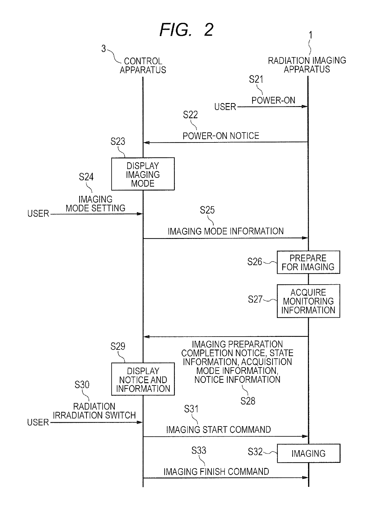
[0028]An example of an embodiment of the present invention is described in detail with reference to the drawings. FIG. 1A and FIG. 1B are diagrams for illustrating an example of a radiation imaging system according to this embodiment. As illustrated in FIG. 1A, the radiation imaging system includes a radiation imaging apparatus 1, a radiation generating apparatus 2 configured to apply radiation to the radiation imaging apparatus 1, and a control apparatus 3 configured to control the radiation imaging apparatus 1 and the radiation generating apparatus 2.

[0029]The radiation imaging apparatus 1 includes a radiation detecting unit 101, an image processing unit 102, a control unit 103, a storage unit 104, a communication unit 105, a monitoring unit 106, and an information outputting unit 108. As illustrated in FIG. 1B, the control unit 103 includes a correction data acquiring unit 107. The control apparatus 3 includes an input unit 301, a display unit 302, and a communication unit 303.

[0...

second embodiment

[0073]An example of an embodiment of the present invention is described in detail with reference to the drawings. Descriptions of the same configurations, functions, and operations as those of the first embodiment described above are omitted, and differences from this embodiment are mainly described.

[0074]FIGS. 7A and 7B are diagrams for illustrating an example of a radiation imaging system according to this embodiment. As illustrated in FIG. 7A, in the radiation imaging system, the radiation imaging apparatus 1 further includes an image analyzing unit 109.

[0075]The image analyzing unit 109 is configured to monitor, as the monitoring information, how much a residual image remains in the image captured by the radiation imaging apparatus 1 (e.g., the radiation image, the exposure image, and the non-exposure image of the object), i.e., to monitor the degree of the residual image. For example, when the imaging mode is transmitted from the control apparatus 3 to the radiation imaging app...


PUM

PropertyMeasurementUnit
temperatureaaaaaaaaaa
lengthaaaaaaaaaa
length of timeaaaaaaaaaa

Abstract

Provided is a radiation imaging apparatus, including: an information outputting unit configured to output state information on a state of the radiation imaging apparatus; a correction data acquiring unit configured to acquire offset correction data through use of image data acquired in an acquisition mode that is set based on the state information; and an image processing unit configured to correct image data acquired by imaging an object through use the offset correction data.

Description

BACKGROUND OF THE INVENTION[0001]Field of the Invention[0002]The present invention relates to a radiation imaging apparatus and a radiation imaging system, which are used for capturing radiation images.[0003]Description of the Related Art[0004]As radiation imaging apparatus, which are configured to capture a radiation image of an object with the use of radiation (e.g., X ray) transmitted through the object, radiation imaging apparatus capable of displaying a radiation image in real time have been widespread. Further, flat-panel radiation imaging apparatus (FPD) have also been proposed.[0005]The FPD includes minute radiation detectors aligned on a quartz glass substrate in matrix. The radiation detectors each include a lamination of a scintillator configured to convert radiation into visible light and a solid-state photodetector in which an amorphous semiconductor is sandwiched by a transparent conductive film and a conductive film. Further, solid-state photodetectors using a photode...

Claims


Application Information

Patent Timeline
Patent Type & Authority Patents(United States)
IPC IPC(8): G06K9/00G01N23/04
CPCG01N23/04G01N2223/401
Inventor ASAI, HIROKI
Owner CANON KK
Features
  • R&D
  • Intellectual Property
  • Life Sciences
  • Materials
  • Tech Scout
  • Unparalleled Data Quality
  • Higher Quality Content
  • 60% Fewer Hallucinations
Learn More