Ball screw device and steering system

a technology of ball screw and steering system, which is applied in the direction of power-driven steering, vehicle components, gearing, etc., can solve the problems of reducing the precision of the shape of the retainer groove, and achieve the effect of suppressing variation or increasing rotational torqu

Active Publication Date: 2019-12-10
JTEKT CORP
View PDF14 Cites 0 Cited by
  • Summary
  • Abstract
  • Description
  • Claims
  • Application Information

AI Technical Summary

Benefits of technology

[0006]It is one object of the present invention to provide a ball screw device and a steering system that suppress variation or increase in rotational torque.
[0008]According to this structure, the distance between the first end of the ball screw nut and the first end of the retainer is set equal to or larger than the distance between a part of the retainer groove that is closest to the second end of the retainer and a part of the ball that is closest to the second end of the ball screw nut. Thus, even when the retainer moves in an axial direction along with rotation of the ball screw nut, the ball is brought into contact with the end of the retainer groove, and therefore the axial movement of the retainer is suppressed. The retainer does not protrude from the ball screw nut, thereby reducing the occurrence of a situation where the retainer is brought into contact with other components provided outside the ball screw nut. Therefore, the variation in the rotational torque of the ball screw device is suppressed.

Problems solved by technology

At the time of bending, the retainer grooves are distorted due to the bending for forming the flange, resulting in a decrease in precision of the shapes of the retainer grooves.

Method used


Image

  • Ball screw device and steering system
  • Ball screw device and steering system
  • Ball screw device and steering system

Examples


Embodiment Construction

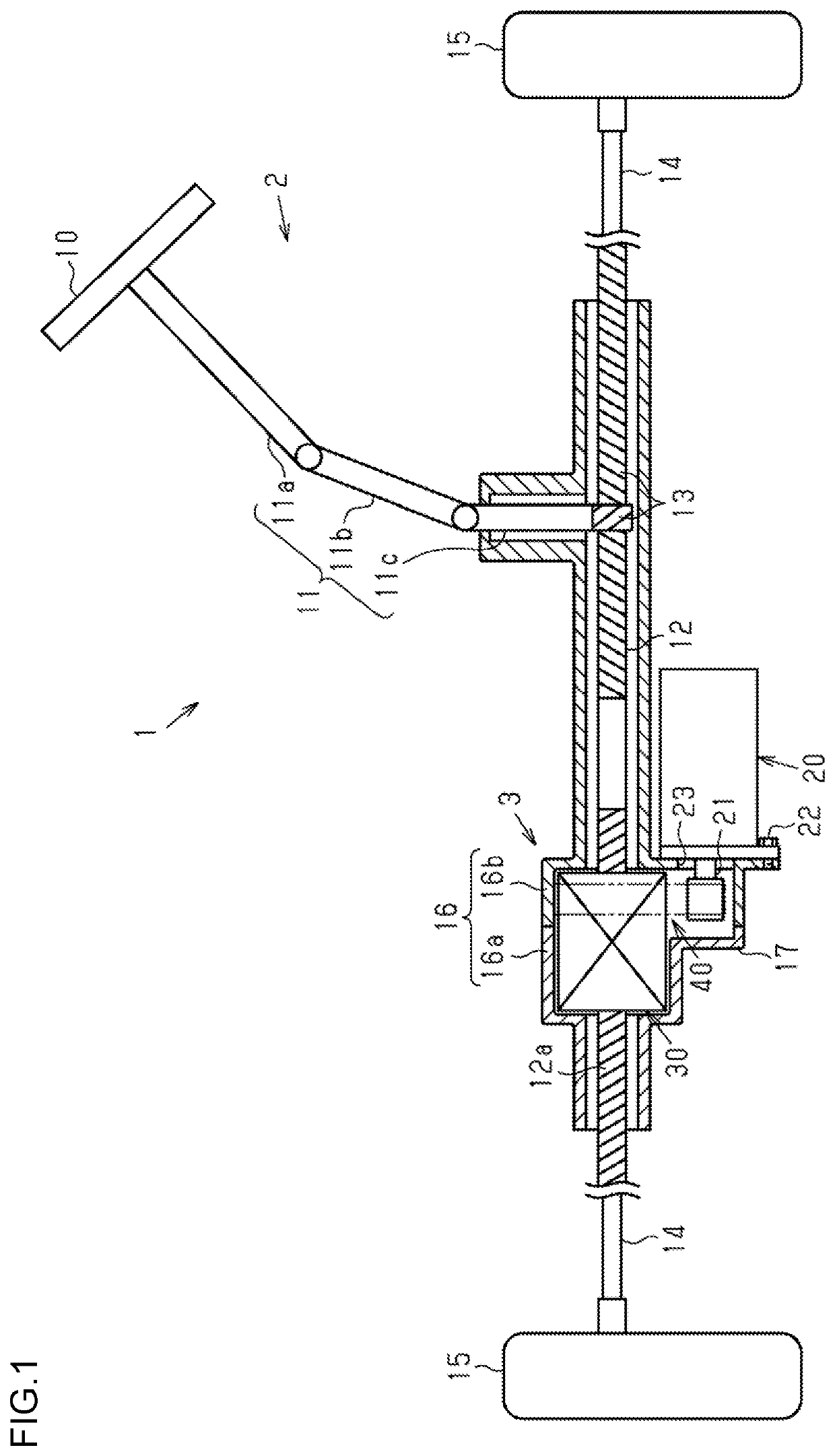
[0018]An electric power steering system (EPS) that is a steering system according to one embodiment of the present invention is described below. As illustrated in FIG. 1, an EPS 1 includes a steering operation mechanism 2 configured to turn steered wheels 15 based on a driver's operation for a steering wheel 10, and an assist mechanism 3 configured to assist the driver's steering operation.

[0019]The steering operation mechanism 2 includes the steering wheel 10 and a steering shaft 11 to be rotated integrally with the steering wheel 10. The steering shaft 11 includes a column shaft 11a coupled to the steering wheel 10, an intermediate shaft 11b coupled to the lower end of the column shaft 11a, and a pinion shaft 11c coupled to the lower end of the intermediate shaft 11b. The lower end of the pinion shaft 11c is coupled to a rack shaft 12 serving as a ball screw shaft through intermediation of a rack and pinion mechanism 13. The lower end (pinion teeth) of the pinion shaft 11c meshes ...


PUM


Abstract

A cylindrical retainer configured to retain balls in a rollable manner is provided inside a ball screw nut. The retainer has retainer grooves each having a shape of an elongated hole that extends in an axial direction of a ball screw shaft so as to be inclined at a predetermined angle. A first end of the ball screw nut and a first end of the retainer, which is one of two ends of the retainer that is closer to the first end of the ball screw nut, are spaced away from each other by a distance. The terminal end of the retainer groove closest to the second end of the retainer and a ball that is closest to the second end of the ball screw nut are spaced away from each other by a distance. The distance is set equal to or larger than the distance.

Description

INCORPORATION BY REFERENCE[0001]The disclosure of Japanese Patent Application No. 2016-112188 filed on Jun. 3, 2016 including the specification, drawings and abstract, is incorporated herein by reference in its entirety.BACKGROUND OF THE INVENTION1. Field of the Invention[0002]The present invention relates to a ball screw device and a steering system.2. Description of the Related Art[0003]There has been known an electric power steering system (EPS) configured to assist a driver's steering operation by converting rotational torque of a motor to a force for causing linear motion of a rack shaft with a ball screw device.[0004]In this ball screw device, the ball screw nut to be rotated by the motor is threadedly engaged with the rack shaft through intermediation of balls. Along with the rotation of the ball screw nut, the balls roll between the ball screw nut and the rack shaft while being rotated in the same direction as that of the ball screw nut. When adjacent balls strike against ea...

Claims


Application Information

Patent Timeline
Patent Type & Authority Patents(United States)
IPC IPC(8): F16H25/22F16H25/20B62D3/06B62D3/04B62D3/02F16H25/18B62D3/08
CPCF16H25/2214B62D3/08B62D3/04F16H25/2204F16H25/22F16H25/18F16H25/20B62D3/02B62D3/06B62D5/0448F16H25/2233
Inventor NAKAYAMA, TAKUYAASAKURA, TOSHIHIROOGAWA, KEISUKE
Owner JTEKT CORP
Why Eureka
Try Eureka