Fuel cell stack

Active Publication Date: 2018-12-20
HONDA MOTOR CO LTD
View PDF2 Cites 5 Cited by
  • Summary
  • Abstract
  • Description
  • Claims
  • Application Information

AI Technical Summary

Benefits of technology

[0018]In the present invention, when the load receiver contacts the contact portion, only the top portion of the expansion of the protrusion contacts the contact portion. Therefore, even in the case where the fuel cell stack has dimensional tolerance and/or production tolerance of component parts, the distances between the portion (a fulcrum point) of the load receiver provided in the separator and the portions

Problems solved by technology

Under the circumstances, since the distance between the portion of the load receiver provided in the separator (fulcrum point) and the portion of the load receiver which contacts

Method used


Image

  • Fuel cell stack
  • Fuel cell stack
  • Fuel cell stack

Examples


Example

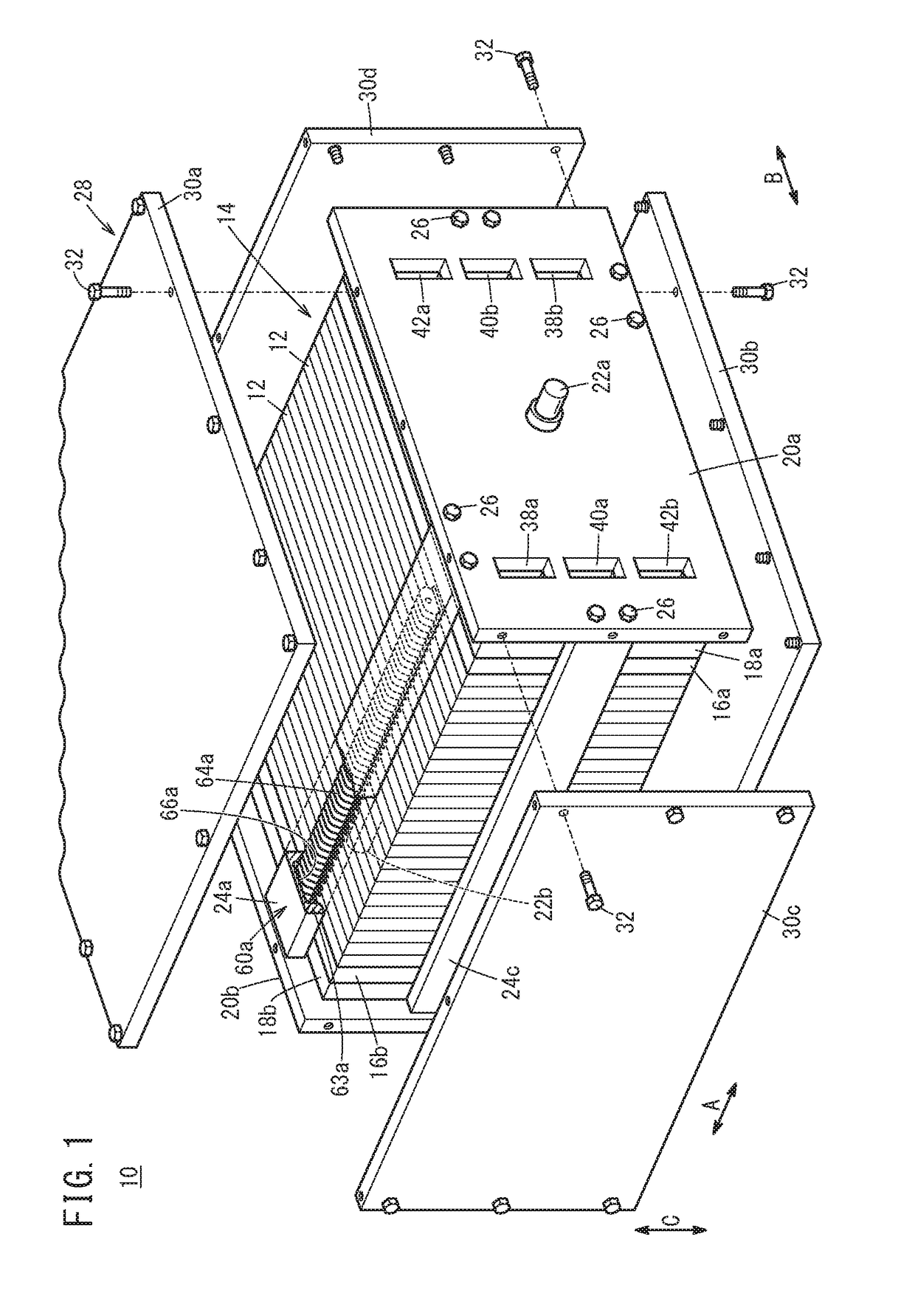
[0027]Hereinafter, preferred embodiments of a fuel cell stack according to the present invention will be described with reference to the accompanying drawings.

[0028]As shown in FIG. 1, a fuel cell stack 10 according to an embodiment of the present invention includes a stack body 14 formed by stacking a plurality of unit cells 12 together in a stacking direction. For example, the fuel cell stack 10 is mounted in a fuel cell automobile in a manner that the stacking direction (indicated by an arrow A) of the plurality of unit cells 12 is oriented in a horizontal direction (vehicle width direction or vehicle length direction) of the fuel cell automobile. It should be noted that the fuel cell stack 10 may be mounted in a fuel cell automobile in a manner that the stacking direction of the plurality of unit cells 12 is oriented in a vertical direction (vehicle height direction) of the fuel cell automobile.

[0029]At one end of the stack body 14 in the stacking direction indicated by the arro...


PUM


Abstract

A fuel cell stack includes a load receiver provided in a first separator, and a contact portion. The load receiver includes a protrusion protruding outward from an outer peripheral portion of the first separator. The protrusion includes a protrusion body positioned at the center in a width direction of the protrusion, and a pair of expansions expanded in the width direction from both ends of the protrusion body in the width direction. When the load receiver contacts the contact portion, only a top portion of the expansion contacts the contact portion.

Description

CROSS-REFERENCE TO RELATED APPLICATION[0001]This application is based upon and claims the benefit of priority from Japanese Patent Application No. 2017-117717 filed on Jun. 15, 2017, the contents of which are incorporated herein by reference.BACKGROUND OF THE INVENTIONField of the Invention[0002]The present invention relates to a fuel cell stack including a stack body formed by stacking a plurality of unit cells together, a load receiver including a protrusion protruding outward from an outer peripheral portion of a separator of each of the unit cells and provided in the separator, and a contact portion provided in an outer peripheral portion of the separator, and spaced from the unit cells.Description of the Related Art[0003]For example, a solid polymer electrolyte fuel cell includes a unit cell (power generation cell). The unit cell is formed by sandwiching a membrane electrode assembly (MEA) between separators. The membrane electrode assembly includes an electrolyte membrane, and...

Claims


Application Information

Patent Timeline
IPC IPC(8): H01M8/2475H01M8/241H01M8/0247H01M8/248
CPCH01M8/2475H01M8/241H01M8/0247H01M8/248H01M2250/20H01M2008/1095Y02E60/50Y02T90/40
Inventor OHMORI, SUGURUTAKAGI, KOSUKE
Owner HONDA MOTOR CO LTD
Why Eureka
Try Eureka