Electro-optical module and projection-type display apparatus

Active Publication Date: 2015-06-04
138 EAST LCD ADVANCEMENTS LTD
View PDF0 Cites 5 Cited by
  • Summary
  • Abstract
  • Description
  • Claims
  • Application Information

AI Technical Summary

Benefits of technology

[0096]As described above, in the electro-optical module 10 in the present embodiment, the frame 60 surrounds the first substrate 51 on the side surfaces 521, 522, and 523 side of the second substrate 52. However, the frame 60 does not exist on the side surface 514 of the side where the protrusion portion 515 of the first substrate 51 is positioned, or at the position facing the side surface 524 of the second substrate 52. For this reason, the frame 60 does not interfere with the wiring material such as the flexible wiring board 40i which is connected to the protrusion portion 515 to be pulled out to the outside.
[0097]In addition, in the present embodiment, the heat dissipation member 30 is disposed between the frame 60 and the electro-optical panel 40, and the heat dissipation member 30 includes the surface of the second substrate 52 side of the protrusion portion 515 of the first substrate 51, the side surface 524 of the second substrate 52, the protrusion surface protruding from the second transparent plate 57 of the second substrate 52, and the frame portion 34 (the first frame portion) facing the side surface 574 of the second transparent plate 57. In addition, the heat dissipation member 30 includes the frame portion 31 (the second frame portion) that extends from one end side of the frame portion 34 toward between the side surface 521 of the second substrate 52 and the frame 60, and the frame portion 32 (the third frame portion) that extends from the other end side of the frame portion 34 toward between the side surface 522 of the second substrate 52 and the frame 60. For this reason, the frame 60 does not exist on the position facing the side surface 514 of the side where the protrusion portion 515 of the first substrate 51 is positioned or the side surface 524 of the second substrate 52. However, at the side where the protrusion portion 515 is positioned, the heat generated in the electro-optical panel 40 after being released to the frame portions 31 and 32 via the frame portion 34 of the heat dissipation member 30, then, can further be released to the frame 60. Therefore, it is possible to suppress the variation of the temperature or the increase of the temperature of the entire electro-optical panel 40 without increasing the size of the electro-optical module 10. Accordingly, it is possible to suppress the deterioration of the electro-optical material layer 450 caused by the increase of the temperature of the electro-optical panel 40.
[0098]Particularly, in a case where the molded article in which the metal layer is provided on the su

Problems solved by technology

In the electro-optical module, when the temperature of the electro-optical panel increases due to heat generation in the electro-optical panel itself or heat generation caused by incidence of a source light, a deterioration in the electro-optical material layer occurs.
Therefore, since it is not possible to dispose a frame on the second substrate with respect to the protrusion portion of the first substrate, in the configuration

Method used


Image

  • Electro-optical module and projection-type display apparatus
  • Electro-optical module and projection-type display apparatus
  • Electro-optical module and projection-type display apparatus

Examples


embodiment 1

Overview of Projection-Type Display Apparatus (an Electronic Apparatus)

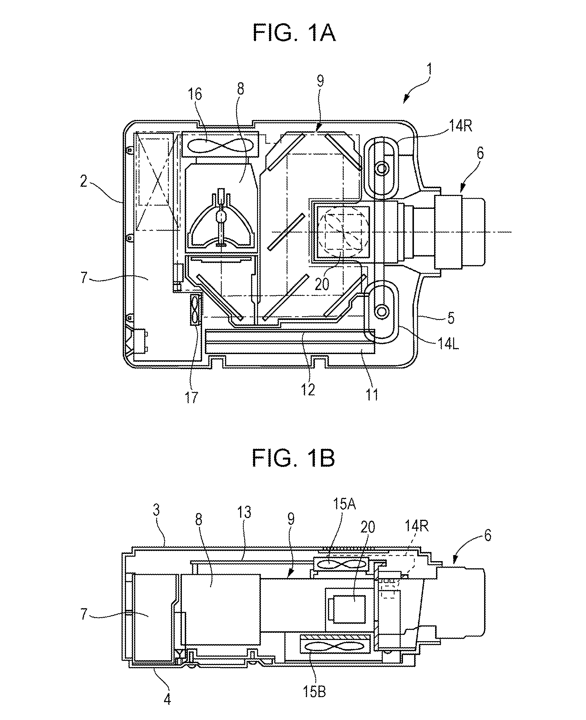
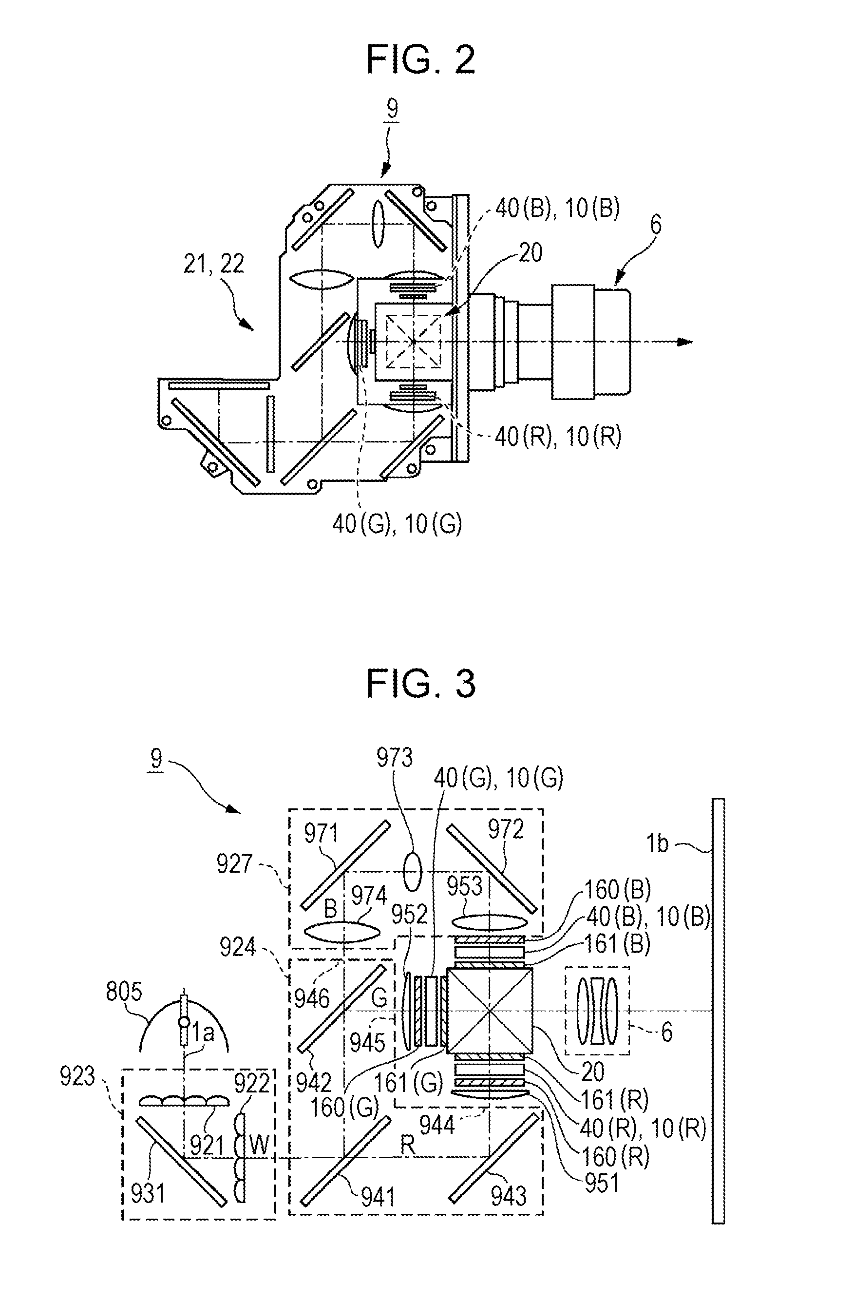
[0047]FIG. 1A and FIG. 1B are explanatory drawings of a projection-type display apparatus as an example of an electronic apparatus to which the invention is applied. FIG. 1A is an explanatory drawing illustrating a planar configuration of a main portion of the projection-type display apparatus, and FIG. 1B is an explanatory drawing illustrating the main portion seen from the side. FIG. 2 is an explanatory drawing illustrating a configuration of an optical unit used in the projection-type display apparatus to which the invention is applied.

[0048]In a projection-type display apparatus 1 illustrated in FIG. 1A and FIG. 1B, in an outer case 2, a power source unit 7 is disposed at the rear side thereof, and a light source lamp unit 8 (light source portion) and an optical unit 9 are disposed at the position adjacent to the power source unit 7 in the front side of the device. In addition, inside of the outer case 2, at ...

modification example 1 of embodiment 1

[0106]FIG. 9A and FIG. 9B are cross-sectional views of the electro-optical module 10 in modification example 1 of Embodiment 1 of the invention. FIG. 9A is a YZ cross-sectional view of the electro-optical module and FIG. 9B is an XZ cross-sectional view of the same. Since the basic configuration in the modification example is similar to that in Embodiment 1, the common portions will be referred to by common signs, and the description thereof will be omitted.

[0107]As illustrated in FIG. 9A and FIG. 9B, in the electro-optical module 10 in the present example also, similarly to Embodiment 1, the heat dissipation member 30 is disposed between the electro-optical panel 40 and the frame 60. In addition, the corner portions 610, 620, 630, and 640 of the frame 60 face the protrusion surface 55 protruding from the first transparent plate 56 of the first substrate 51 and the side surfaces 561, 562, 563, and 564 of the first transparent plate 56.

[0108]In the present example, differently from E...

modification example 2 of embodiment 1

[0110]FIG. 10A and FIG. 10B are cross-sectional views of an electro-optical module 10 in the modification example 2 of Embodiment 1 of the invention. FIG. 10A is a YZ cross-sectional view of the electro-optical module and FIG. 10B is an XZ cross-sectional view of the same. Since the basic configuration in the modification example is similar to that in Embodiment 1, the common portions will be referred to by the same signs, and the description thereof will be omitted.

[0111]As illustrated in FIG. 10A and FIG. 10B, in the electro-optical module 10 in the present example also, similarly to Embodiment 1, the heat dissipation member 30 is disposed between the electro-optical panel 40 and the frame 60. In the present example, the size of the first transparent plate 56 is larger than that of the first substrate 51, and the surface of the first substrate 51 side of the first transparent plate 56 includes a protrusion surface protruding from the first substrate 51 over the entire circumferenc...


PUM


Abstract

In an electro-optical module, a frame does not exist on a side surface of a first substrate on the side where a protrusion portion is positioned or at a position of a second substrate facing a side surface. Between the frame and an electro-optical panel, a heat dissipation member that includes a frame portion is disposed, which faces a surface of the protrusion portion of the first substrate on the second substrate side, a side surface of the second substrate and the side surface of the second transparent plate. In addition, the heat dissipation member includes frame that extend toward between the side surfaces of the second substrate and the frame from both end sides of the frame portion.

Description

BACKGROUND[0001]1. Technical Field[0002]The present invention relates to an electro-optical module used in an electronic apparatus such as a projection-type display apparatus, and the projection-type display apparatus that includes the electro-optical module.[0003]2. Related Art[0004]When an image is displayed in an electronic apparatus such as a projection-type display apparatus, light is used which is modulated by an electro-optical panel such as a liquid crystal panel. The electro-optical panel has a configuration in which, for example, an electro-optical material layer such as a liquid crystal layer is provided between a first substrate and a second substrate. In addition, the first substrate includes a protrusion portion that protrudes from the second substrate, and on a surface of the protrusion portion of the second substrate side, a terminal to which a flexible wiring is connected is provided. In addition, the electro-optical panel is accommodated inside of the frame (frame ...

Claims


Application Information

Patent Timeline
IPC IPC(8): G02F1/1333H04N5/74H04N9/31
CPCG02F1/133385H04N5/7441H04N9/3144G02F1/133308G03B21/16
Inventor HIRABAYASHI, HIDEKAZU
Owner 138 EAST LCD ADVANCEMENTS LTD
Why Eureka
Try Eureka