Optical block reinforcing member, optical block and optical module

a technology of optical modules and reinforcing members, applied in the field of optical block reinforcing members, optical block and optical modules, can solve the problems of no optical module with high reliability that uses low-cost rigid boards as circuit boards, and is more expensive than a normal rigid board

Inactive Publication Date: 2008-09-25
HITACHI METALS LTD
View PDF2 Cites 91 Cited by
  • Summary
  • Abstract
  • Description
  • Claims
  • Application Information

AI Technical Summary

Benefits of technology

[0015]It is an object of the invention to provide an optical module that uses a low-cost rigid board as a circuit board and can reduce stress generated at a connection part between an optical block and the circuit board. An optical block reinforcing member and an optical block are also provided in relation to the above object.

Problems solved by technology

However, the circuit board 142 used by the optical module 141 is formed with a rigid flex board which is more expensive than a normal rigid board.
Until now, no optical module with high reliability has been developed that uses the low-cost rigid board as the circuit board and can prevent stress from being generated at the connection part between the lens and the circuit board.

Method used


Image

  • Optical block reinforcing member, optical block and optical module
  • Optical block reinforcing member, optical block and optical module
  • Optical block reinforcing member, optical block and optical module

Examples


first embodiment

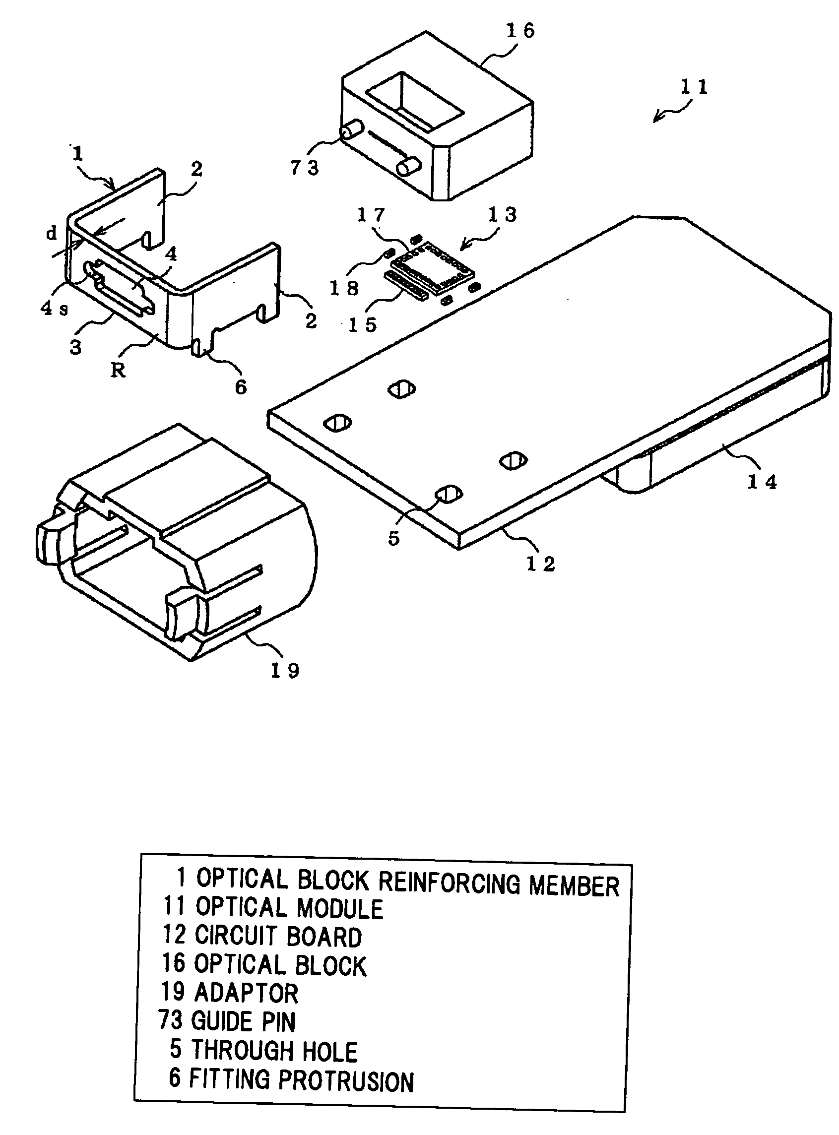
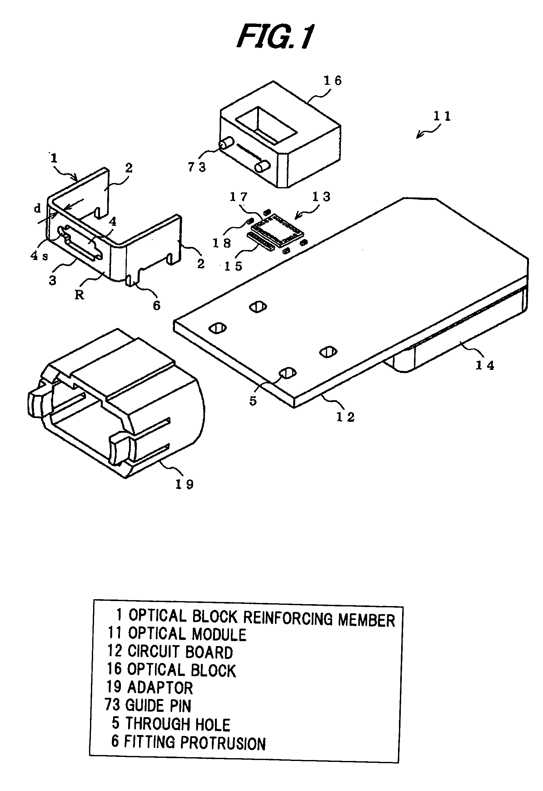
[0099]Referring to FIGS. 1 to 3, an optical module in a first preferred embodiment of the invention will be explained that uses an optical block reinforcing member 1.

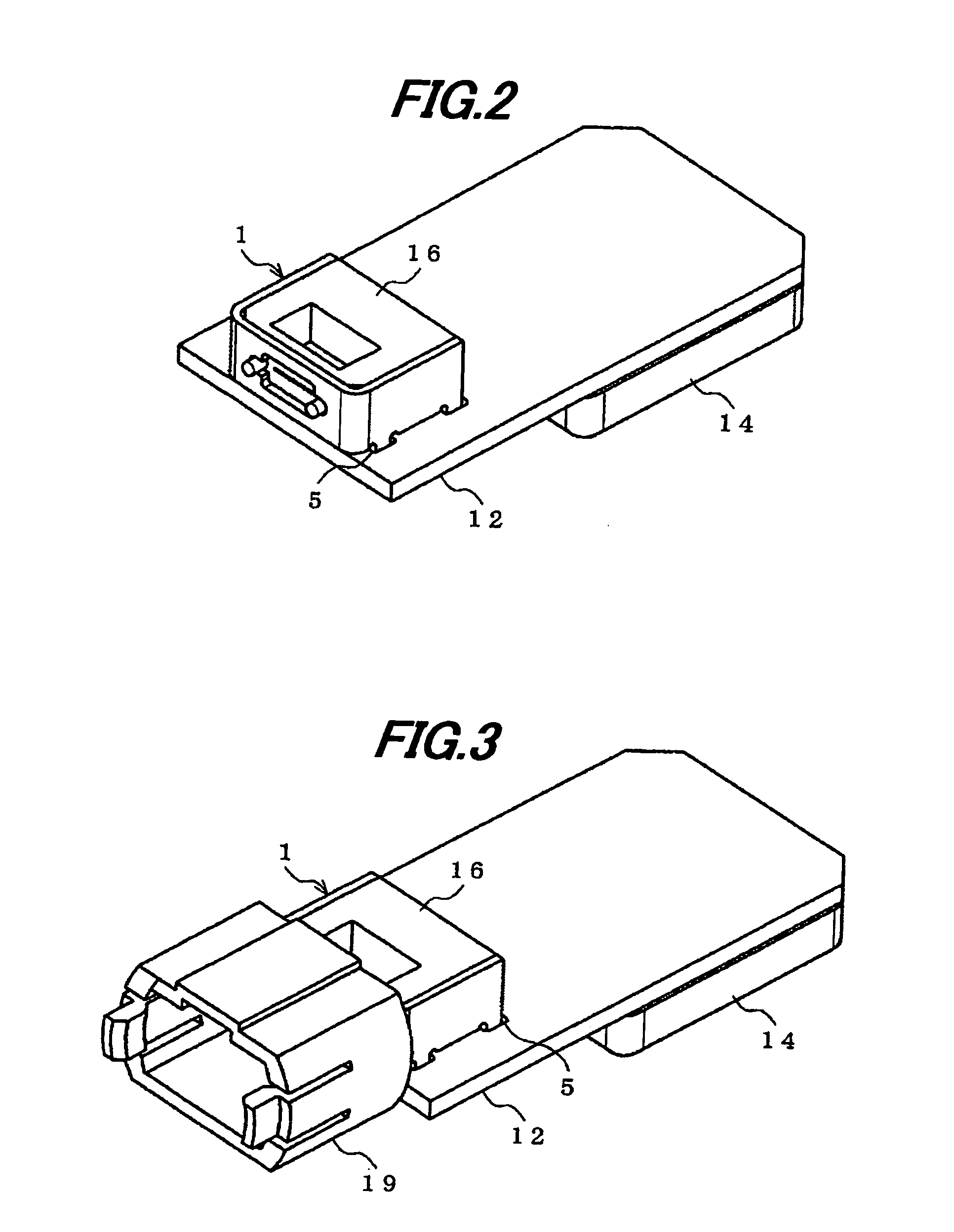
[0100]FIG. 1 is an exploded perspective view showing a main part of the optical module using the optical block reinforcing member in the first preferred embodiment according to the invention. FIG. 2 is a perspective view showing the optical module in FIG. 1 where an optical block and the optical block reinforcing member are mounted on a circuit board. FIG. 3 is a perspective view showing the optical module in FIG. 2 with an adaptor for an optical connector.

[0101]As shown in FIGS. 1 to 3, the optical module 11 is a multi-channel pluggable optical transceiver that can be attached to a network device (information system device) such as a switching hub and a media converter.

[0102]As described below, an example of a transmission optical transceiver is given that is of 12-channel type used for SNAP12 (12-channel parallel tran...

second embodiment

[0139]An optical module in a second preferred embodiment of the invention will be explained that uses the optical block reinforcing member 1.

[0140]As shown in FIGS. 10 to 13, the optical module 101 of this embodiment is provided with a sub-board 102 made of ceramics such as alumina in addition to the components of the optical module 11 (of the first embodiment) as shown in FIGS. 1 to 8. In other words, the optical module 101 is formed such that the LD element module 15 and the electronic parts are mounted on the sub-board 102 and the sub-board 102 is disposed between the optical block reinforcing member 1 and the circuit board 12.

[0141]The sub-board 102 is formed of a material (e.g., ceramics with a Young's modulus higher than the circuit board 12) harder than the circuit board 12. It has a size sufficient to allow all of the optical block 16 with the optical block reinforcing member 1, the optical parts and electrical parts to be mounted thereon. The sub-board 102 is provided with ...

third embodiment

[0147]Referring to FIGS. 14 to 16, an optical module in a third preferred embodiment of the invention will be explained that uses an optical block reinforcing member 1.

[0148]FIG. 14 is an exploded perspective view showing a main part of the optical module using the optical block reinforcing member in the third preferred embodiment according to the invention. FIG. 15 is a perspective view showing the optical module in FIG. 14 where an optical block and the optical block reinforcing member are mounted on a circuit board. FIG. 16 is a perspective view showing the optical module in FIG. 15 with an adaptor for an optical connector.

[0149]As shown in FIGS. 14 to 16, the optical module 211 is a multi-channel pluggable optical transceiver that can be attached to a network device (information system device) such as a switching hub and a media converter.

[0150]As described below, an example of a transmission optical transceiver is given that is of 12-channel type used for SNAP12 (12-channel par...


PUM


Abstract

An optical module includes a circuit board, an optical element mounted on the circuit board, an electronic parts for driving the optical element, an optical block optically coupled with the optical element and adapted to be connected to an optical connector, wherein the optical block includes a protrusion including a guide pin for connecting the optical block to the optical connector, and a receiving portion formed nearly cylindrical around a root of the guide pin and having a receiving surface on which the optical block abuts the optical connector, an optical block reinforcing member including an upper lid for covering the optical block, and sidewalls for covering both sides of the optical block arranged perpendicular to a width direction of the optical connector, wherein the optical block reinforcing member includes a separate body from the optical block and is adapted to be attached on the optical block, and a casing for housing the circuit board, the optical element, the electronic parts, the optical block and the optical block reinforcing member.

Description

[0001]The present application is based on Japanese patent application Nos. 2007-061798 and 2007-295556 filed on Mar. 12, 2007 and Nov. 14, 2007, respectively, the entire contents of which are incorporated herein by reference.BACKGROUND OF THE INVENTION[0002]1. Field of the Invention[0003]This invention relates to an optical block reinforcing member that is used in an optical module to transmit and / or receive optical signals as Ethernet (registered trademark) signal being gigabit-class in signal transmission speed so as to reinforce an optical block connected to an optical connector, the optical block for reducing a pressing force occurred when connecting the optical connector to the optical block, and the optical module composed of the optical block reinforcing member and the optical block.[0004]2. Description of the Related Art[0005]In recent years, the bandwidth of the Internet increases. Especially, Ethernet (registered trademark) spreads as a core technology for domestic LAN and...

Claims


Application Information

Patent Timeline
Patent Type & Authority Applications(United States)
IPC IPC(8): G02B6/12G02B6/36
CPCG02B6/4201G02B6/4292G02B6/4249G02B6/4214G02B6/428G02B6/4284
Inventor ISHIGAMI, YOSHIAKITAMURA, KENICHI
Owner HITACHI METALS LTD
Why Eureka
Try Eureka