Lighting system and remote control method therefor

a technology of remote control and light source, which is applied in the direction of point-like light sources, lighting and heating apparatuses, light sources, etc., can solve the problems of inefficient energy-saving method and system, continuous modulation of light (at high frequencies, typically megahertz) to incorporate identification codes, and luminaries emit light, etc., to improve energy efficiency and improve emc characteristics

Active Publication Date: 2010-09-30
KONINKLIJKE PHILIPS ELECTRONICS NV
View PDF2 Cites 91 Cited by
  • Summary
  • Abstract
  • Description
  • Claims
  • Application Information

AI Technical Summary

Benefits of technology

[0005]It is an objective of the invention to provide a lighting system, control method, and remote control device of the kind set forth with improved energy efficiency. It is a further objective to provide a lighting system and control method having improved EMC characteristics. Moreover, it is an objective of the invention to provide a lighting system and a control method that avoid non requested light distribution when user control is not desired. At least one of these objects is achieved with the remote control device according to the invention as defined in claim 1, the lighting system as defined in claim 6, and the control method as defined in claim 11.

Problems solved by technology

However, a drawback of the solution described in WO2006 / 111927 is that all lighting arrangements need to transmit identification codes at all times, in order to make them visible to the remote control device.
Still, even at such dimmed levels, WO2006 / 111927 discloses an energy inefficient method and system.
Continuous modulation of the light (at high frequencies, typically megahertz) to incorporate the identification codes forms a further drawback, as it contributes to electromagnetic emissions and EMC issues.
In addition, appreciating that certain desired lighting effects prescribe one or more luminaries to be turned ‘off’, the necessity to have these luminaries emit light (even at low intensities) contributes to undesired light distributions.

Method used


Image

  • Lighting system and remote control method therefor
  • Lighting system and remote control method therefor

Examples


Embodiment Construction

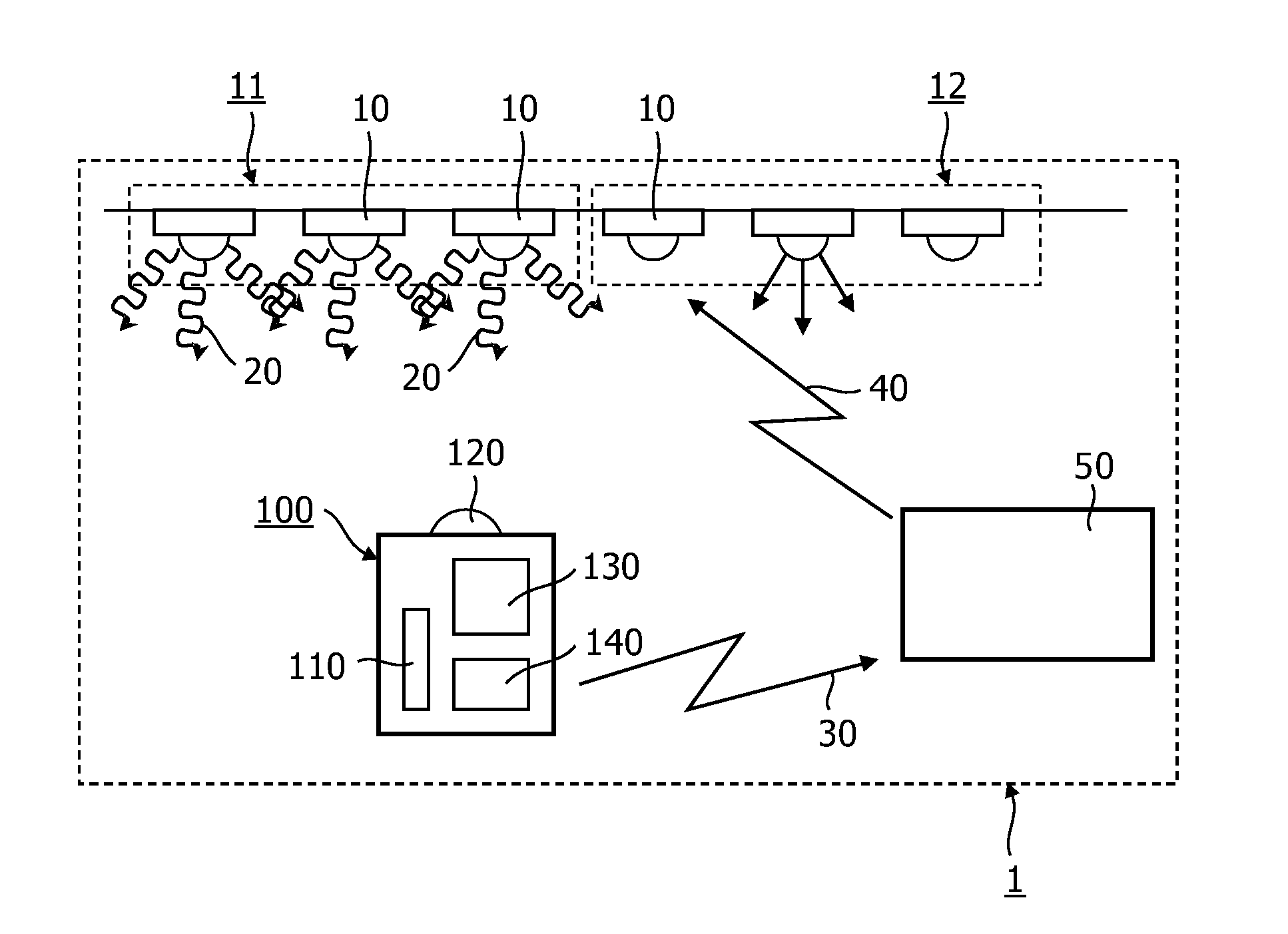
[0026]FIG. 1 shows a lighting system 1 of the kind set forth. The system comprises a plurality of light modules 10. These modules may comprise one or more light sources, such as LEDs, oLEDs, fluorescent tubes, HID bulbs, etc. The light modules 10 comprise a modulator capable of modulating the light emitted to comprise light module identification codes 20. The lighting system 1 further comprises a remote control device 100, capable of detecting the light emitted by the light modules 10 with a light detector 120 and deriving amongst others the identification codes 20 from the light detected. The remote control device 100 further comprises control data generation means 130, arranged to generate control data intended for the lighting system 1 based on the light detected and the identification codes 20 derived. The control data may comprise the identification codes, data relating to a property of the light detected (such as colour point, intensity, etc) and user defined commands. Prefera...


PUM


Abstract

Proposedis a remote control device (100), arranged to control a lighting system(1). The lighting system comprises a plurality of light-modules (10) capable of emitting modulated light comprising light module identification codes (20). The remote controldevice (100) comprises a sensor (110) arranged to switch the light modules (10) from an operational mode (210) in which the light emitted by the light modules (10) is non-5 modulated to a control mode (230) in which the light emitted by the light modules (10) is modulated. Advantageously, the invention provides a lighting system with improved energy efficiencyand EMC characteristics.

Description

FIELD OF THE INVENTION[0001]The invention relates to a remote control device arranged to control a lighting system comprising a plurality of light modules capable of emitting modulated light comprising light module identification codes. Furthermore, the invention relates to a lighting system comprising a plurality of light modules arranged to emit modulated light comprising light module identification codes. Moreover, the invention relates to a method to control such a lighting system, the method comprising the steps (i) providing a remote control device, and (ii) checking whether the remote control device is operated by a user. Intuitive controlling a lighting effect in a desired location suitably makes use of such remote control devices, lighting systems and control methods.BACKGROUND OF THE INVENTION[0002]An embodiment of a remote control device of the kind set forth is known from WO2006 / 111927, assigned to the same applicant. That document discloses a control method of an advanc...

Claims


Application Information

Patent Timeline
Patent Type & Authority Applications(United States)
IPC IPC(8): H05B37/02F21Y101/00
CPCH05B37/0272H05B37/0245H05B47/175H05B47/19H05B39/04H05B45/60H05B45/37
Inventor VAN DE SLUIS, BARTEL MARINUSFERI, LORENZO
Owner KONINKLIJKE PHILIPS ELECTRONICS NV
Why Eureka
Try Eureka