Control device for internal combustion engine

Active Publication Date: 2018-01-25
HITACHI ASTEMO LTD
View PDF12 Cites 5 Cited by
  • Summary
  • Abstract
  • Description
  • Claims
  • Application Information

AI Technical Summary

Benefits of technology

[0011]According to the present invention, it is possible to suppress a variation in fuel injection quantity caused by injection of a boosted voltage during charge, without shifting a requested injection timing when there is a n

Problems solved by technology

However, when the multiple times of injection are performed in a relatively sho

Method used


Image

  • Control device for internal combustion engine
  • Control device for internal combustion engine
  • Control device for internal combustion engine

Examples


Example

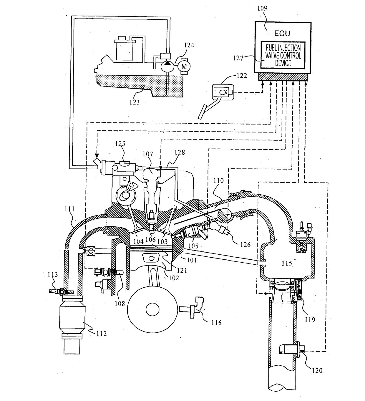
[0021]Hereinafter, the configuration and operation of a system including an ECU (a control device for an internal combustion engine) according to an embodiment of the present invention will be described with reference to the drawings. FIG. 1 is a diagram illustrating a basic configuration of a system including an ECU according to an embodiment of the present invention.

[0022]In FIG. 1, air sucked into an internal combustion engine (101) passes through an air flow meter (AFM) (120), is sucked in the order of a throttle valve (119) and a collector (115), and is thereafter supplied to a combustion chamber (121) via an intake pipe (110) and an intake valve (103) provided in each cylinder.

[0023]Meanwhile, the fuel is sent from a fuel tank (123) to a high-pressure fuel pump (125) of the internal combustion engine (101) by a low-pressure fuel pump (124), and the high-pressure fuel pump (125) controls the fuel pressure to a desired pressure, based on the control command value from an engine ...


PUM


Abstract

Provided is a control device for an internal combustion engine, the control device enabling the suppression of variations in the amount of fuel injected by injection while the boost voltage is charging, without offsetting the injection timing. A boost circuit (211) boosts a first voltage supplied from a battery (201), and supplies a boosted second voltage to a fuel injection device (214). Switches (212, 213) switch the second voltage supplied to the fuel injection device from the booster circuit on and off. Computation devices (204, 207) control the switches. Each computation device comprises: an estimation unit that, before the initial fuel injection in a combustion cycle, estimates the second voltage for all of the fuel injection times in the combustion cycle; and a correction unit that corrects the amount of fuel injected for each fuel injection time depending on the estimated second voltage.

Description

TECHNICAL FIELD[0001]The present invention relates to a control device for an internal combustion engine.BACKGROUND ART[0002]Conventionally, in a system for a fuel injection, in one operation cycle of a cylinder of an internal combustion engine, fuel supply is performed by multiple times of fuel injection (multi-stage injection) to a combustion chamber from a fuel injection device having a fuel injection valve electromagnetically driven.[0003]In such a fuel injection device, a boost power supply is generally configured to include a boost circuit including an inductive element and a switching element, and a capacitor which stores the boosted electric power. When the fuel injection valve is energized from the boost power supply, power is supplied by discharge from the capacitor. Therefore, when power is energized from the boost power supply, the voltage drops due to the discharge of the capacitor.[0004]After discharging the capacitor, the power is charged by the boost circuit and retu...

Claims


Application Information

Patent Timeline
IPC IPC(8): F02D41/40
CPCF02D41/40F02D2200/50F02D41/26F02D41/20F02D41/402F02M69/046F02D2041/2003F02D2041/2051F02D2041/2058F02D2200/0602Y02T10/40
Inventor KIMURA, SHINGOHORII, TOMOAKINAGASE, MITSURUYAMAOKA, SHIROUKUSAKABE, RYOITAYA, TAKAKI
Owner HITACHI ASTEMO LTD
Why Eureka
Try Eureka