Pump housing with inline valve

a plunger pump and inline valve technology, applied in the direction of pump components, positive displacement liquid engines, liquid fuel engine components, etc., can solve the problems of multiple major cross-bore blocks and y-blocks, the individual bores of the plunger pump fluid end housing are subject to fatigue, and the feeding of the plunger bore cavity, etc., to reduce stress, reduce stress, and eliminate the loss of fluid energy

Active Publication Date: 2020-01-07
ALTIS INVESTMENTS LLC
View PDF4 Cites 6 Cited by
  • Summary
  • Abstract
  • Description
  • Claims
  • Application Information

AI Technical Summary

Benefits of technology

[0012]The fluid end housing of the present invention comprises multiple fluid chambers with each chamber having a suction bore that is aligned with the plunger bore, commonly referred to as an “in-line configuration,” i.e., the bores are aligned. As such the axis of the suction bore is substantially co-linear with the plunger bore. The configuration of the suction bore of the present invention eliminates the loss of fluid energy present in fluid end housings of the prior art in which the suction fluid flow must undergo a right-angle turn to fill the plunger bore or inner cavity of the housing.
[0013]The fluid chamber of the housing of the present invention also includes a discharge bore with the centerline of said discharge bore being perpendicular to the plunger bore centerline. In the present invention, the peak stress at the intersection of the plunger, suction, and the discharge bores is significantly reduced by two design features. The first feature is co-linear arrangement of the plunger bore and the suction bore that eliminates the concentration of stresses at these two bores typical of fluid end housings of the prior art as shown in FIGS. 3A, 3B, 4, 7A, and 7B.
[0014]The second design feature is a rectangular or square cross-section of the plunger bore. The corners of the rectangular or square cross section are filleted with generously sized radii, resulting in four flat or planar areas on each side of the rectangular or square cross section. The intersection of the discharge port wholly within one of the planar areas of the rectangular or square plunger chamber significantly reduces the stress at said intersection. In the embodiments disclosed herein, the radius of said fillets at the corners of said rectangular cross-section ranges from 50 percent to 70 percent of the radius of the plunger packing bore.

Problems solved by technology

Each individual bore in a plunger pump fluid end housing is subject to fatigue due to alternating high and low pressures which occur with each stroke of the plunger cycle.
Both Cross-Bore blocks and Y-blocks have several major disadvantages when used to pump heavy slurry fluids as typically utilized in oilfield fracturing service.
A first disadvantage is related to the feeding of the plunger bore cavity on the suction stroke of the pump.
The second disadvantage of Cross-Bore blocks and Y-blocks relates to the large intersecting curved areas where the various bores intersect.
Because the intersection curve changes slope through three-dimensional space, this intersection cannot be easily chamfered or filleted by conventional machining techniques that would mitigate these stresses to a smaller extent.
Indeed, complex computer finite element stress analysis calculations indicate that chamfering or filleting the corner intersection has minimal effect on reducing the stresses at this corner intersection.
Y-Block fluid end housing designs, such as those illustrated in FIG. 4, do reduce this pitch, but the reduction is insufficient to prevent cyclic fatigue failure of the fluid end housing when subjected to high pressure and long pumping cycles.

Method used


Image

  • Pump housing with inline valve
  • Pump housing with inline valve
  • Pump housing with inline valve

Examples


Embodiment Construction

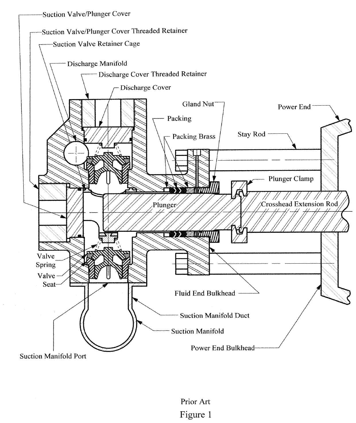
[0040]FIG. 8 schematically illustrates a cross-section of an embodiment of the fluid end housing assembly 100 of the present invention showing its connection to a power section by stay rods. As opposed to fluid end housing of the prior art as illustrated in FIG. 1, fluid end housing 1 of the present invention is configured with the suction manifold 5 mounted in a position on the fluid end housing opposite the power end of the pump.

[0041]The housing 1 of the present invention features multiple fluid chambers 2 with each chamber 2 containing multiple bores. The plunger 310 may be of a two-piece design as illustrated in FIG. 8 with a plunger pressure end 311 and a plunger clamp end 312. A two-piece plunger facilitates easier maintenance by field mechanics. Alternately a one-piece plunger, not shown, could be utilized. However, a one-piece plunger would require removal of the fluid end housing assembly 100 from the power end assembly for routine maintenance on components of assembly 100...


PUM


Abstract

A plunger pump fluid end housing assembly comprising: a fluid end housing, multiple plungers, a single in-line suction valve and seat corresponding with each said plunger, a discharge valve and seat corresponding with each said plunger; wherein axis of said suction valve and seat are parallel with said plunger, and the suction manifold is positioned to feed the fluid chamber opposite the power end of the fluid end. Plunger chamber of said fluid end housing is square or rectangular in cross section with large fillets at corners and flats between said fillets. Said flats are approximately equal in width to radii of said fillets.

Description

FIELD OF THE INVENTION[0001]The invention relates generally to high-pressure plunger pumps used, for example, in oil field operations. More particularly, the invention relates to an internal bore configuration that improves flow, improves cylinder filling, and incorporates structural features for stress-relief in high-pressure plunger pumps.BACKGROUND[0002]Engineers typically design high-pressure oil field plunger pumps in two sections: the (proximal) power section and the (distal) fluid section. The power section usually comprises a crankshaft, reduction gears, bearings, connecting rods, crossheads, crosshead extension rods, etc. Commonly used fluid sections usually comprise a plunger pump fluid end housing with multiple fluid chambers, each chamber having a suction valve in a suction bore, a discharge valve in a discharge bore, an access bore, and a plunger in a plunger bore, plus high-pressure seals, retainers, etc. FIG. 1 is a cross-sectional schematic view of a typical fluid en...

Claims


Application Information

Patent Timeline
Patent Type & Authority Patents(United States)
IPC IPC(8): F04B1/14F04B53/16F04B1/12F04B53/10
CPCF04B1/0421F04B53/10F04B53/16F04B53/1087F04B1/143
Inventor BLUME, GEORGE H
Owner ALTIS INVESTMENTS LLC
Why Eureka
Try Eureka