Hob with central downward removal of cooking vapors through suction

a technology of suction slits and hobs, which is applied in the field of hobs, can solve the problems of high maintenance costs, disadvantages of known hobs with suction slits on both sides and on the back, and entail marked manufacturing and material costs, so as to prevent cooking vapors from rising and expanding, and low manufacturing, assembly, maintenance and operating costs.

Active Publication Date: 2020-07-21
BRUCKBAUER WILHELM
View PDF49 Cites 3 Cited by
  • Summary
  • Abstract
  • Description
  • Claims
  • Application Information

AI Technical Summary

Benefits of technology

[0011]The object of the present invention is to provide a hob with a device for removing cooking vapors through suction in a direction lying vertically below the plane of the hob, which does not use the surfaces on the countertop carrying the hob that are located on both sides and on the back of the hob, but rather allows them to be used for temporary storage or similar purposes, which reliably prevents cooking vapors from rising and expanding both in the central area of the hob and in its edge areas, which entails especially low manufacturing, assembly, maintenance and operating costs, which requires no separate mounting frame for securing the enveloping countertop, which is especially efficient in terms of the energy used for suction purposes, and which generates very little noise during its operation.

Problems solved by technology

This hob known from prior art with suction slits provided on both sides and on the back is disadvantageous in particular because the countertop that carries the hob cannot be completely used for temporary storage or similar purposes, at least right to the side of the hob.
This hob encompassed by prior art with suction slits provided on both sides and on the back is also disadvantageous because the two lateral and rear suction flows cancel each other out completely or at least partially, above all in the especially important area in the center of the hob, so that cooking vapors that arise there are not exposed to any effective suction flow, thus allowing them to expand and rise unimpeded.
Another disadvantage to this hob originating from prior art with suction slits provided on both sides and on the back is that it entails marked manufacturing and material costs, in particular due to the design of the three suction devices and the foul-air duct system connected with the latter.
The maintenance costs for this known hob are also especially high, in particular since it has three grease filters that have to be maintained.
Since strong suction flows are released at the same time through all suction slits in this known hob with suction slits provided on both sides and on the back when the cooking vapor suction device is activated, the energy expenditure required for removing cooking vapors through suction is there especially high, giving this known hob a noticeably low efficiency.
Another important disadvantage to the known hob with cooking vapor suction slits provided on both sides and on the back is that it requires a material and time-intensive assembly of the hob on the countertop carrying the hob by means of a separate mounting frame, while bridging the cooking vapor suction slits on both sides and on the back.

Method used


Image

  • Hob with central downward removal of cooking vapors through suction
  • Hob with central downward removal of cooking vapors through suction
  • Hob with central downward removal of cooking vapors through suction

Examples


Embodiment Construction

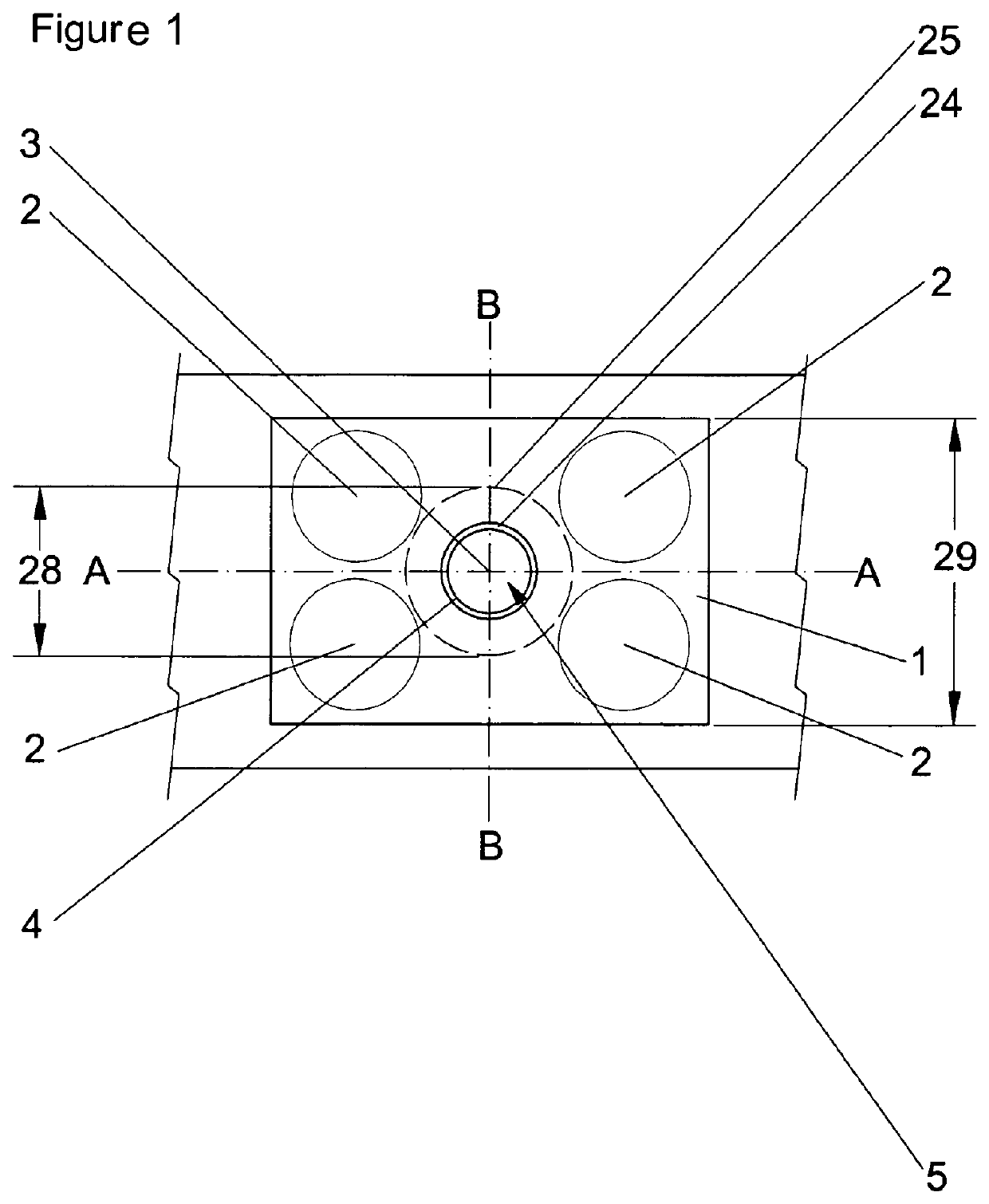
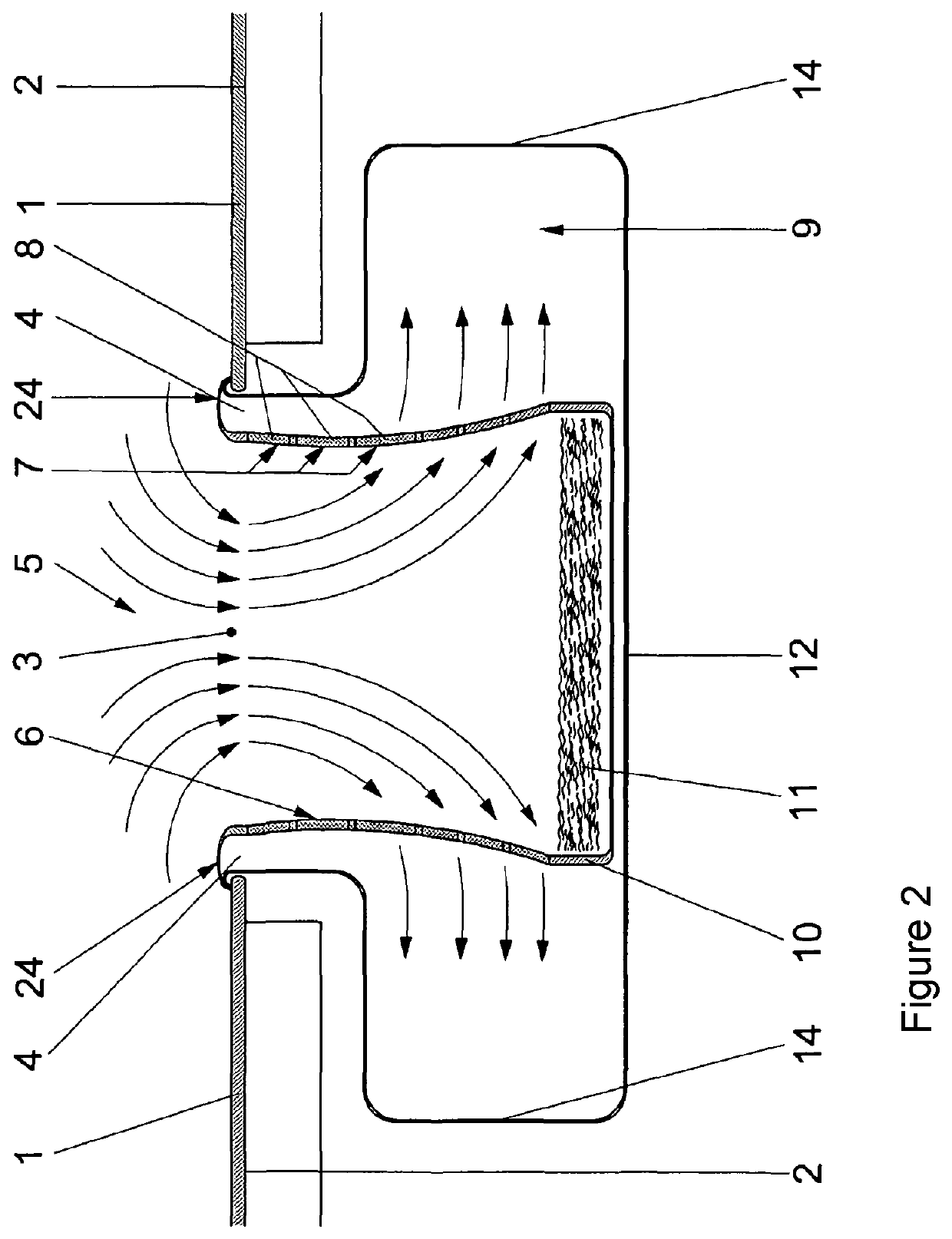
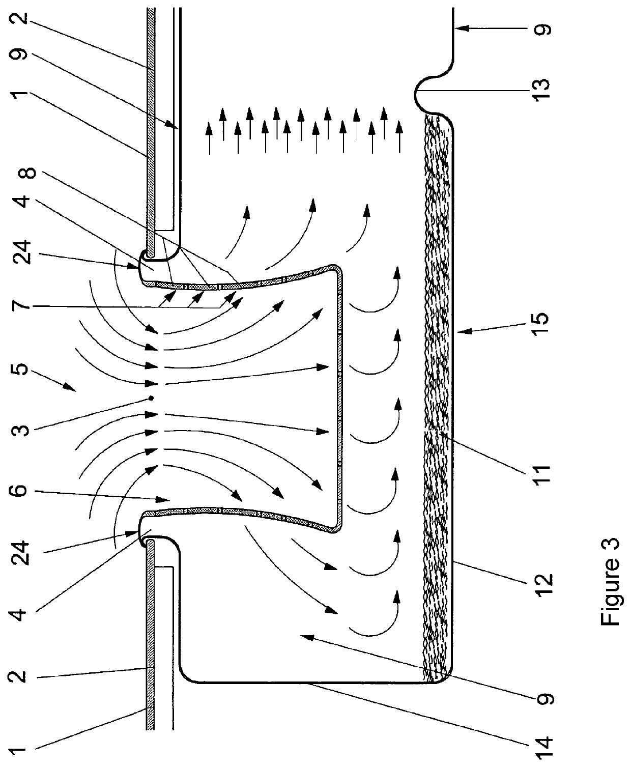
[0033]As a consequence, the present invention relates to a hob (1) with one or more cooking locations (2), which as viewed from above exhibits one or more recesses (4) only in the area (25) around its geometric center (3), but not in its edge areas.

[0034]As a rule, these recesses (4) are connected with one or more devices (5) for removing cooking vapors through suction, wherein these devices (5) for removing cooking vapors through suction downwardly remove the cooking vapors that arose or arise above the cooking location(s) (2) by suction in a direction pointing vertically below the hob (1).

[0035]In general, the diameter (28) of the area (25) for the one or several recesses (4) around the geometric area center (3) of the hob (1) can measure between 10% and 90% of the overall width (29) of the hob (1), preferably between 15% and 85%, in particular between 20% and 80% of the overall width (29) of the hob (1). The shape of the one or more recesses (4) as viewed from above can preferabl...


PUM


Abstract

A hob (1) with one or more cooking locations (2), which, as viewed from above, exhibits one or more recesses (4) only in the area (25) around its geometric center (3), which are respectively connected with one or more devices (5) for removing cooking vapors through suction. These devices (5) for removing cooking vapors through suction downwardly remove the cooking vapors that arise above the cooking locations (2) by suction in a direction vertically below the hob (1), and such a hob (1), which in the assembly unit is designed with a device (36) for operating the hob (2) and downwardly removing cooking vapors by suction.

Description

CROSS REFERENCE TO RELATED APPLICATIONS[0001]This application is a continuation under 37 CFR 1.53(b) of prior U.S. patent application Ser. No. 14 / 114,351 filed Oct. 28, 2013, and claims the benefit (35 U.S.C. § 120 and 365(c)) of International Application PCT / DE2012 / 000458 filed Apr. 28, 2012, which designated inter alia the United States and which claims the priority of German Patent Application DE 20 2011 005 698.8 filed Apr. 28, 2011, the entire contents of each application are incorporated herein by reference.FIELD OF THE INVENTION[0002]The present invention pertains to a hob with one or more cooking locations with the hob comprising one or more recesses only in an area around its geometric center, which are connected with one or more devices for removing cooking vapors through suction, wherein the devices for removing cooking vapors through suction downwardly to remove the cooking vapors that arose or arise above the cooking locations by suction in a direction pointing vertical...

Claims


Application Information

Patent Timeline
Patent Type & Authority Patents(United States)
IPC IPC(8): F24C15/20
CPCF24C15/2042F24C15/2035F24C15/10
Inventor BRUCKBAUER, WILHELM
Owner BRUCKBAUER WILHELM
Why Eureka
Try Eureka