Vibration motor

a technology of vibration motor and motor body, which is applied in the direction of dynamo-electric machines, electrical equipment, supports/enclosements/casings, etc., can solve the problems of impact noise, amplitude of vibrating components is greater, and the vibration component cannot realize the rapid back-and-forth movemen

Active Publication Date: 2020-10-06
AAC TECH PTE LTD
View PDF13 Cites 6 Cited by
  • Summary
  • Abstract
  • Description
  • Claims
  • Application Information

AI Technical Summary

Benefits of technology

[0029]The damping piece can be limited and prevented from shifting during vibration and the instable damping force and the extra noise can be avoided by arranging the restricting protrusion on the counterweight additionally in the vibration motor of the present disclosure. Moreover, the damping piece can be assembled in the vibration motor stably; thus the vibration motor has stable performance and high reliability.

Problems solved by technology

When the vibration motor runs, a sufficient driving force should be guaranteed, otherwise the return time of vibration of the vibrating component is too long and results that the vibrating component cannot realize the rapid back-and-forth movement.
However, when the driving force is too great, the amplitude of the vibrating component will be greater, and the vibrating component will impact the housing of the vibration motor to produce impact noise.
However, the performance of the whole vibration motor may be affected, and the vibration motor may have low reliability as a result of instable damping force and extra noise due to weak assembling of the damping piece and the vibrating component because the damping piece may offset easily during vibration.

Method used


Image

  • Vibration motor
  • Vibration motor
  • Vibration motor

Examples


first embodiment

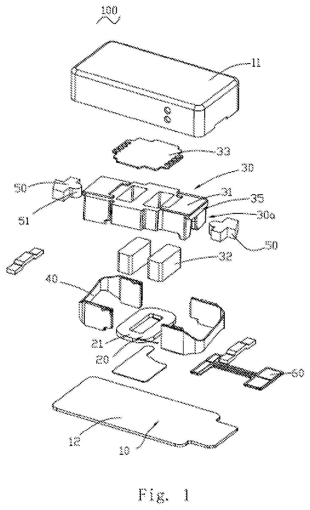
[0015]Referring to FIGS. 1-4, a vibration motor 100 in accordance with the present disclosure comprises a housing 10 having an accommodating space, a fixed component 20, a vibrating component 30 and an elastic connecting piece 40 accommodated in the housing 10. The housing 10 comprises a housing body 11 and a cover plate 12 covering the housing body 11 for forming the accommodating space. The fixed component 20 is fixed on the cover plate 12. The vibrating component 30 comprises a counterweight 31 whose two sided parts are connected to the elastic connecting piece 40. Therefore, the vibrating component 30 is suspended in the accommodating space by the elastic connecting piece 40 for being capable of vibrating along a direction parallel to a length direction of the cover plate 12.

[0016]The fixed component 20 comprises coils 21 fixed on the cover plate 12, and the coils 21 are connected with an external circuit (not shown) by a circuit board 60 arranged on the cover plate 12 in order ...

embodiment 1

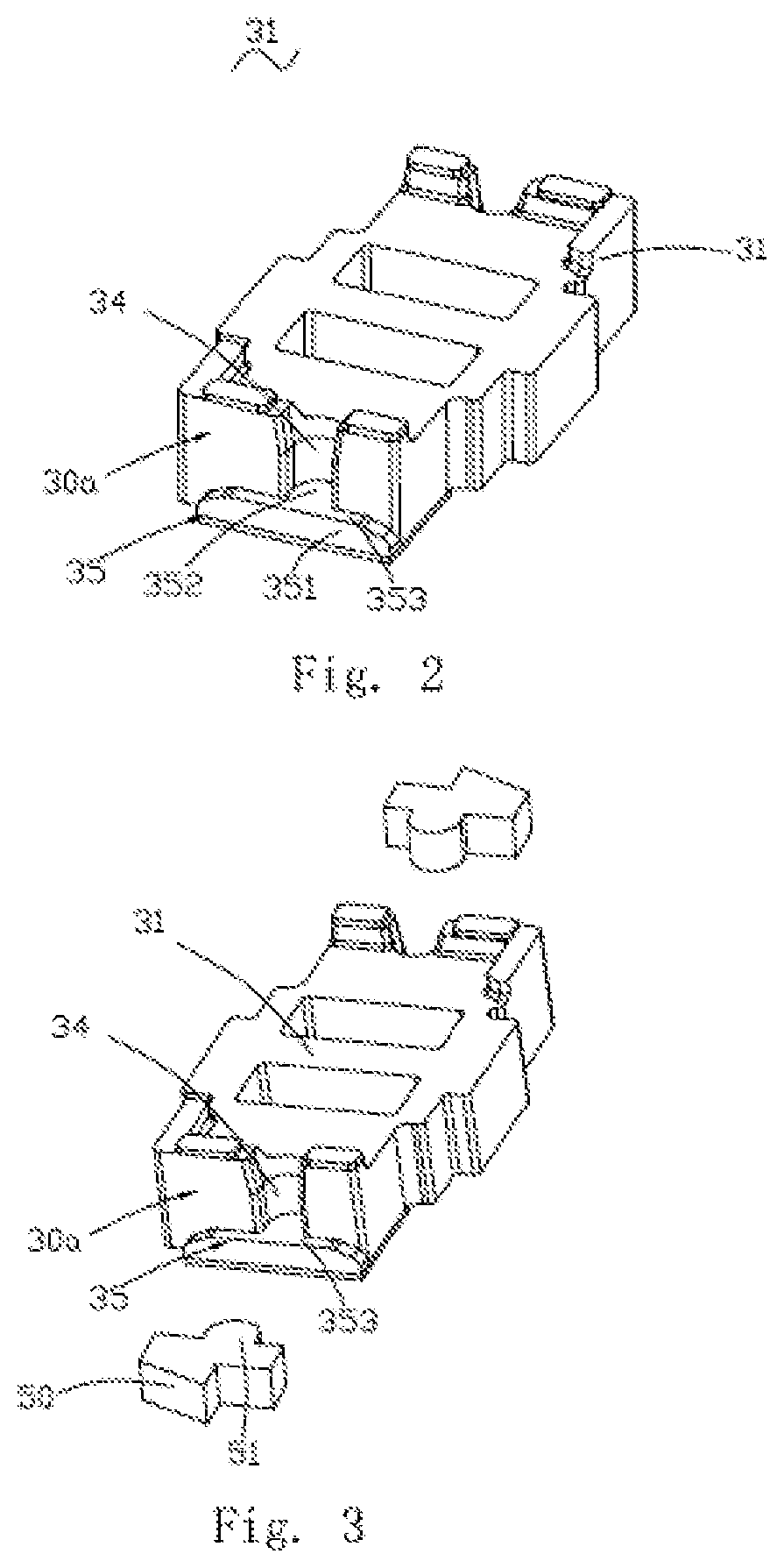
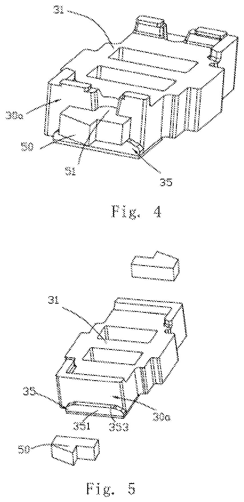
[0026]Of course, the two restricting protrusions 35 can be arranged at interval identically as for the vibration motor in Embodiment 1 in order to facilitate holding the damping piece 50 among two restricting protrusions 35 more stably.

[0027]The exploded view of the counterweight and the damping piece of a fourth embodiment of the present disclosure is shown in FIG. 7. Unlike the first embodiment shown in FIGS. 1-4, the insertion part is formed on the counterweight, while the slot is arranged on the damping piece in this embodiment; as shown in FIG. 7 specifically, the damping piece 50 is provided with a slot 51′ in this embodiment; while a restricting protrusion 35′ and an insertion part 36′ matching with the slot 51′ are formed in the way of extending on the counterweight 31 facing the elastic connecting piece, wherein the restricting protrusion 35′ has a bearing surface 353′ to which the insertion part 36′ is adhered. The distance among the insertion part 36′ and the elastic conn...


PUM


Abstract

A vibration motor is disclosed. The vibration motor includes a housing; an elastic connecting piece; a fixed component; a vibrating component comprising a counterweight suspended in the housing by the elastic connecting piece; and a damping piece accommodated in the housing and fixed on the counterweight. One of the fixed component and the vibrating component includes coils, and the other includes a magnet. The counterweight includes a restricting protrusion extending from a side facing the elastic connecting piece for abutting against and restricting the damping piece.

Description

FIELD OF THE INVENTION[0001]The invention is related to the technology of vibrators, and especially relates to a vibration motor for providing tactile feedbacks.DESCRIPTION OF RELATED ART[0002]The portable consumer electronic products are favored by more and more people along with development of the electronic technologies, such as mobile phone, handheld game player, navigation unit or handheld multimedia entertainment equipment, etc. The vibration feedback, which is taken as one feedback form of the portable consumer electronic product, has been extended to provide the tactile feedback related to application program and scene, etc. gradually from the initial and most fundamental coming call prompt, etc. While the motor is the primary element offering vibration feedback in the mobile equipment and usually comprises a rotary motor, a piezoelectric motor, a linear motor, etc., wherein the linear motor has the absolute advantage on the aspect of offering the tactile feedback related to...

Claims


Application Information

Patent Timeline
Patent Type & Authority Patents(United States)
IPC IPC(8): H02K33/16H02K5/24H02K33/18
CPCH02K5/24H02K33/16H02K33/18
Inventor WU, NACHAI, ZHILINSHAO, YANLING, FANGHUA
Owner AAC TECH PTE LTD
Why Eureka
Try Eureka