Check patentability & draft patents in minutes with Patsnap Eureka AI!

Power generator

a power generator and power supply technology, applied in the direction of electric generator control, electric motor control, emergency protective circuit arrangement, etc., can solve the problems of omitting setting or changing the value, affecting the operation of the power generator, so as to reduce the voltage to be measured, simplify the configuration of the voltage measurement unit, and reduce the withstanding voltage

Active Publication Date: 2020-12-29
YAMABIKO CORP
View PDF4 Cites 0 Cited by
  • Summary
  • Abstract
  • Description
  • Claims
  • Application Information

AI Technical Summary

Benefits of technology

This configuration enables the breaker to consistently provide optimal tripping characteristics, preventing overcurrent or overload issues while reducing the need for manual adjustments and thermal relay calibration, enhancing protection and user convenience.

Problems solved by technology

This makes adjustment work very troublesome.
Further, since the adjustment is manually performed, an operator may cause errors in an adjusted value of the current adjustment knob, or may omit setting or changing the value.
Then, the breaker cannot have appropriate tripping characteristics.
However, even when the thermal relay is used, adjusting the interrupting current characteristics of the thermal relay is required region by region, which causes the problem of the adjustment work described above.
However, this brings about the problem similar to the case where the fixed value is used.

Method used


Image

  • Power generator
  • Power generator
  • Power generator

Examples


Embodiment Construction

[0036]An embodiment of the present disclosure will be described in detail with reference to the accompanying drawings. The following description of a preferred embodiment is merely exemplary one in nature and does not intend to limit the present disclosure, applications or use thereof.

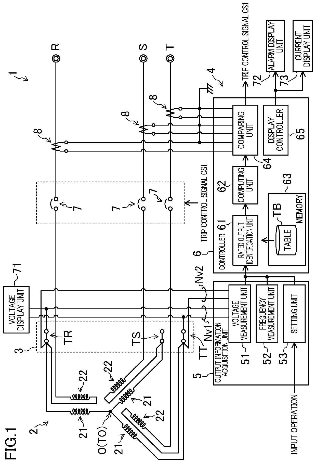
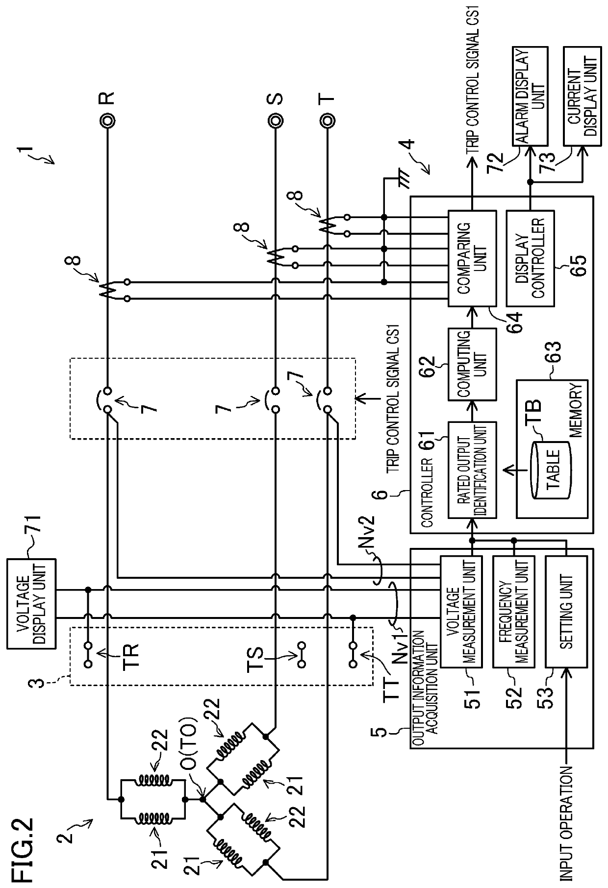
[0037]FIGS. 1 and 2 illustrate a schematic configuration of a power generator 1 according to the embodiment. The power generator 1 according to the present embodiment is configured to be able to supply three-phase AC output of a first voltage V1 (e.g., of a 400 V class) and three-phase AC output of a second voltage V2 (e.g., of a 200 V class) to three-phase output terminals R, S, and T in a switchable manner. As illustrated in FIGS. 1 and 2, the power generator 1 includes a three-phase winding 2 (e.g., an armature winding) serving as a power-generating component, an output switching unit 3 for switching the output of the three-phase winding 2, an overcurrent detection substrate 4, and a display unit. T...


PUM


Abstract

A power generator includes: an output information acquisition unit which acquires output information including power-generating component capacity information indicative of a capacity of a power-generating component and output frequency information indicative of an output frequency of the power generator; an ammeter which measures a current flowing through a distribution path; a breaker provided in the distribution path; and a controller. The controller calculates an allowable current based on the output information, and controls the breaker to interrupt the distribution path when a current measured by the ammeter exceeds the allowable current.

Description

CROSS-REFERENCE TO RELATED APPLICATIONS[0001]This is a continuation of International Application No. PCT / JP2018 / 3503 filed on Feb. 2, 2018, which claims priority to Japanese Patent Application No. 2017-067851 filed on Mar. 30, 2017. The entire disclosures of these applications are incorporated by reference herein.TECHNICAL FIELD[0002]The present disclosure relates to a power generator outputting electric power generated by a power-generating component.BACKGROUND ART[0003]Japanese Unexamined Patent Publication No. 2008-172919 discloses a power generator configured to compare a current value set in a current detection circuit including a thermal relay with a current value inputted from a current transformer, and operate a voltage trip device when the current value inputted from the current transformer exceeds the set current value.[0004]To make such a power generator usable in different regions (e.g., different countries), the output of the power generator requires adjustment to be su...

Claims


Application Information

Patent Timeline
Patent Type & Authority Patents(United States)
IPC IPC(8): H02H7/06H02P9/02H02H1/00
CPCH02H7/06H02H1/0007H02P9/02H02H1/0092H02H3/08H02P9/00H02P29/027
Inventor SUMIKAWA, TAISHI
Owner YAMABIKO CORP
Features
  • R&D
  • Intellectual Property
  • Life Sciences
  • Materials
  • Tech Scout
  • Unparalleled Data Quality
  • Higher Quality Content
  • 60% Fewer Hallucinations
Learn More