Positioning apparatus and method of positioning by generation of DRR image from X-ray CT image data

a positioning apparatus and image data technology, applied in the field of positioning apparatus to position a patient, can solve the problems of long positioning time, long time needed for positioning, and high work load on the operator for a conventional manual positioning, so as to improve radiotherapy throughput and reduce work load. the effect of the operator's work load

Active Publication Date: 2019-10-08
SHIMADZU CORP
View PDF58 Cites 5 Cited by
  • Summary
  • Abstract
  • Description
  • Claims
  • Application Information

AI Technical Summary

Benefits of technology

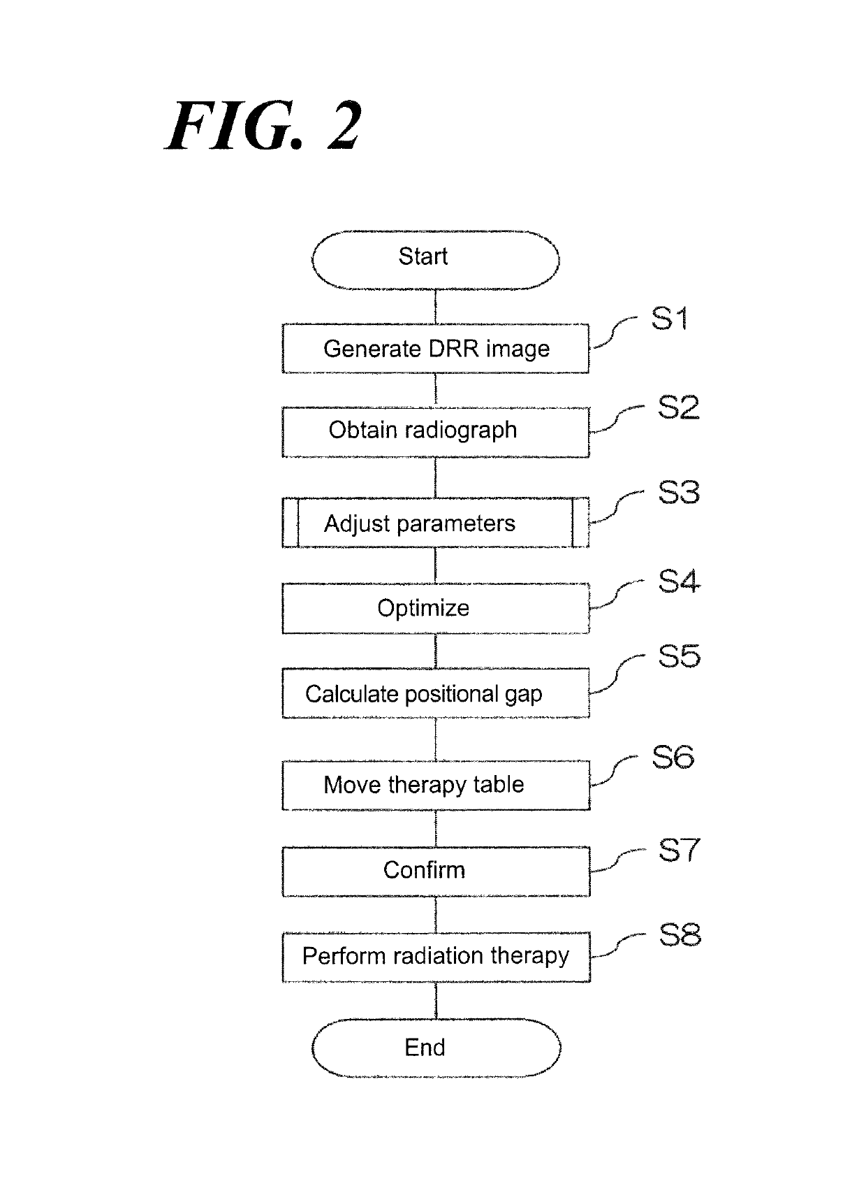
[0021]According to the aspect of the first invention and the fourth invention, an initial position of the initial fluoroscopic projection parameters can be automatically acquired using the DRR image and the radiograph taken prior to beginning the optimization operation by the optimization element. Accordingly, the workload on the operator for a conventional manual positioning can be reduced. In addition, the rough positional gap between the DRR image and the radiograph is calculated automatically, so that e.g., even when the first visit for the divisional radiation therapy is made, the radiotherapy throughput can be improved because such conventional manual step of adjusting the rough positioning could be skipped. Further, a manual operation for positioning by the operator is skippable, so that an accuracy level relative to the positioning of the patient can be performed with a high reproducibility regardless skills and experiences of the operator and in addition, the time needed to position the patient can be shortened. And the patient-time requirement for the radiation treatment can be cut, so that lessening the accuracy level of the positioning due to the move of the patient because of incapability of keeping the same posture (position) during positioning thereof can be suppressed and in addition, an arduous effort of the patient to keep the same posture (position) can be soothed.
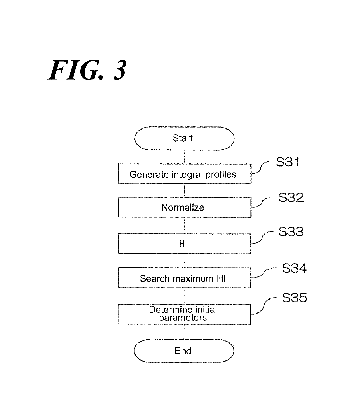
[0022]According to the aspect of the second invention and the fifth invention, comparison between 1-dimensional integral profiles in the same direction of the DRR image and the radiograph is executed, so that a search for the position, at which similarity between images is highest, can be completed in a higher speed than executing the direct comparison between DRR image, which is a 2-dimensional image, and the radiograph. In addition, a mal-effect on the accuracy level of the positioning due to a noise component of each image can be reduced based on such integration.
[0023]According to aspects of the third invention and the sixth invention, a histogram intersection that calculates the similarity of between histograms, given the 1-dimensional integral profiles are histograms, is applied relative to the comparison between the DRR image and the radiograph, so that a strong and high speed search for the position, at which the similarity is highest, can be completed with regards to the difference of quality of images between the DRR image and the radiograph, the difference caused by radiography with-or-without a radiotherapy table or a collimator, elements other than the patient, in each image, and the difference between concentrations.

Problems solved by technology

In addition, it is undesirable that the accuracy level of the positioning to be accomplished, which must be in the relationship with the position of radiotherapy, varies depending on the skill level of the operator.
In addition, according to the conventional method set forth above, the time needed for positioning has been tending to be longer.
In such cases, problems concerning to the individual operator discretion as to the positioning of the patient and that it takes a long time for positioning.

Method used


Image

  • Positioning apparatus and method of positioning by generation of DRR image from X-ray CT image data
  • Positioning apparatus and method of positioning by generation of DRR image from X-ray CT image data
  • Positioning apparatus and method of positioning by generation of DRR image from X-ray CT image data

Examples


Embodiment Construction

[0039]Reference will now be made in detail to embodiments of the invention. Wherever possible, same or similar reference numerals are used in the drawings and the description to refer to the same or like parts or steps. The drawings are in simplified form and are not to precise scale. The word ‘couple’ and similar terms do not necessarily denote direct and immediate connections, but also include connections through intermediate elements or devices. For purposes of convenience and clarity only, directional (up / down, etc.) or motional (forward / back, etc.) terms may be used with respect to the drawings. These and similar directional terms should not be construed to limit the scope in any manner. It will also be understood that other embodiments may be utilized without departing from the scope of the present invention, and that the detailed description is not to be taken in a limiting sense, and that elements may be differently positioned, or otherwise noted as in the appended claims wi...


PUM


Abstract

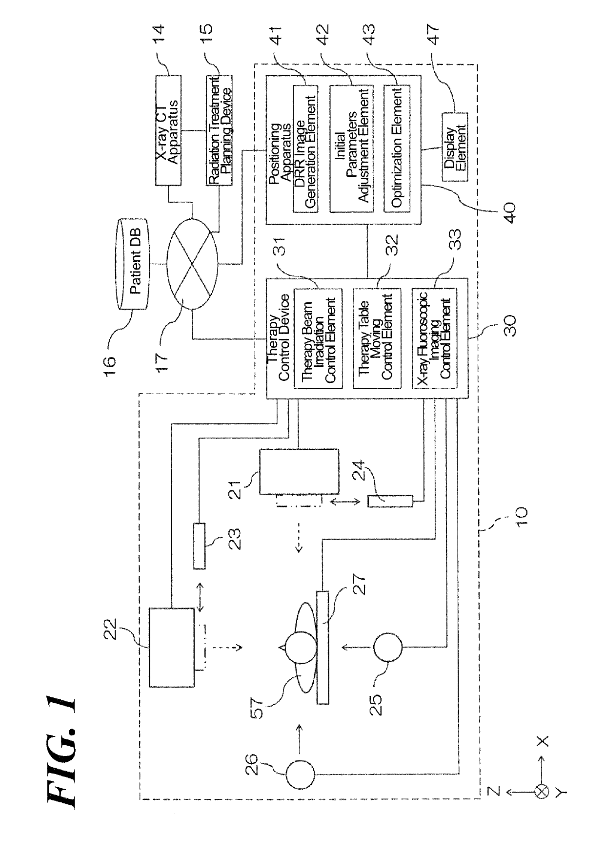
A positioning apparatus automatically performs a patient positioning calculation at high speed and a positioning method. A positioning apparatus 40 has, as functional components, a DRR image generation element 41 that generates the DRR image based on the CT image data, an optimization element 43 that calculates the positional gap of the patient 57 by optimizing the fluoroscopic projection parameters; and an initial parameter adjustment element 42 that changes the initial position of the fluoroscopic projection parameters prior to optimization of fluoroscopic projection parameters with regard to the rotatable and translation of the CT image data relative to the optimization element 43.

Description

CROSS REFERENCE TO RELATED APPLICATIONS[0001]This application relates to, but does not claim priority from, JP 2014-190101 filed Sep. 18, 2014, the entire contents of which are incorporated herein by reference.FIGURE SELECTED FOR PUBLICATION[0002]FIG. 1BACKGROUND OF THE INVENTIONField of the Invention[0003]The present invention relates to a positioning apparatus to position a patient when a radiation treatment is performed on the patient and a method of positioning therefor.Description of the Related Art[0004]The radiation relative to a radiation therapy, in which the radiation including an X-ray, an electron beam, a corpuscular radiation and so forth is irradiated to the affected area including a tumor of the patient and so forth, must be accurately irradiated to the affected area. When the radiation therapy is performed by using a radiation therapy apparatus, the radiation treatment planning is prepared prior to the radiotherapy treatment. And when the radiation therapy is actuall...

Claims


Application Information

Patent Timeline
Patent Type & Authority Patents(United States)
IPC IPC(8): A61N5/10G06T7/00A61B6/03G06T11/00A61B6/04G06T7/73A61B6/00
CPCA61B6/04A61B6/5205A61B6/5211G06T7/73A61B6/035A61N5/1049A61B6/032A61B6/52G06T7/0012G06T11/005G06T2207/20068A61N2005/1061A61N2005/1062G06T2207/10124G06T2207/10121
Inventor TAKAHASHI, WATARUMORI, SHINICHIRO
Owner SHIMADZU CORP
Why Eureka
Try Eureka