Error measurement method for machine tool and machine tool

Active Publication Date: 2022-05-24
OKUMA CORP
View PDF4 Cites 0 Cited by
  • Summary
  • Abstract
  • Description
  • Claims
  • Application Information

AI Technical Summary

Benefits of technology

[0020]The disclosure allows automatically sensing the measurement result of the large disturbance regardless of the shape of the target of the masterwork and performing the

Problems solved by technology

The motion accuracies are transferred to a shape of the workpiece and cause shape and dimensional errors of the workpiece.
However, in the method, a plane of the masterwork is set as the measurement target, and the plane does not have a predetermined length, such as diameter of a sphere or a hole.
Accordingly, lengths of predetermined parts of the target cannot be measured, and a measurement error cannot be determined based on a variation of errors between the measured values and the calibrat

Method used


Image

  • Error measurement method for machine tool and machine tool
  • Error measurement method for machine tool and machine tool
  • Error measurement method for machine tool and machine tool

Examples


Example

[0025]The following describes embodiments of the disclosure based on the drawings.

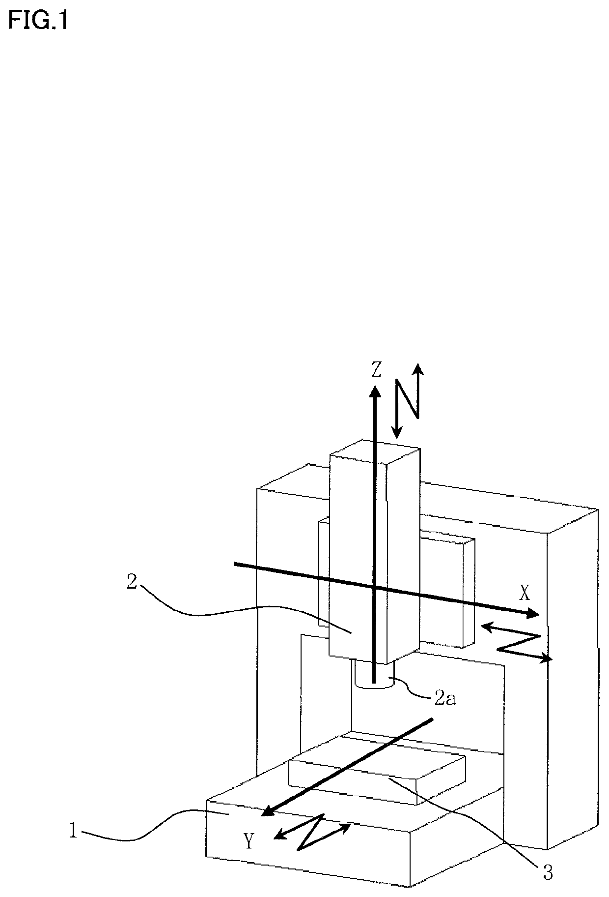
[0026]A numerical control machine tool of FIG. 1 will be described as an example of an applied machine. However, the machine related to the disclosure may be another machine tool, such as a multitasking machine, a lathe, and a grinder.

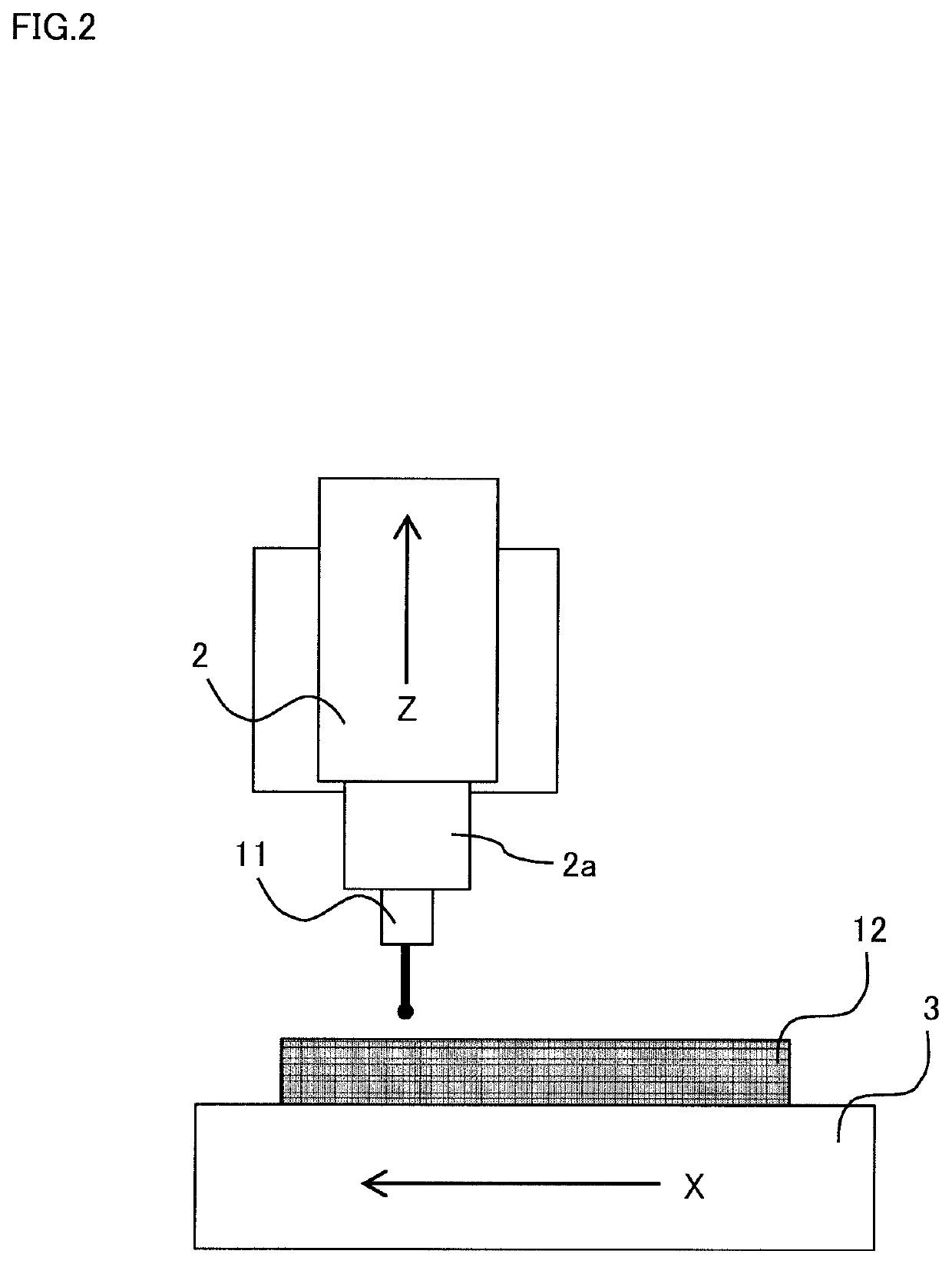
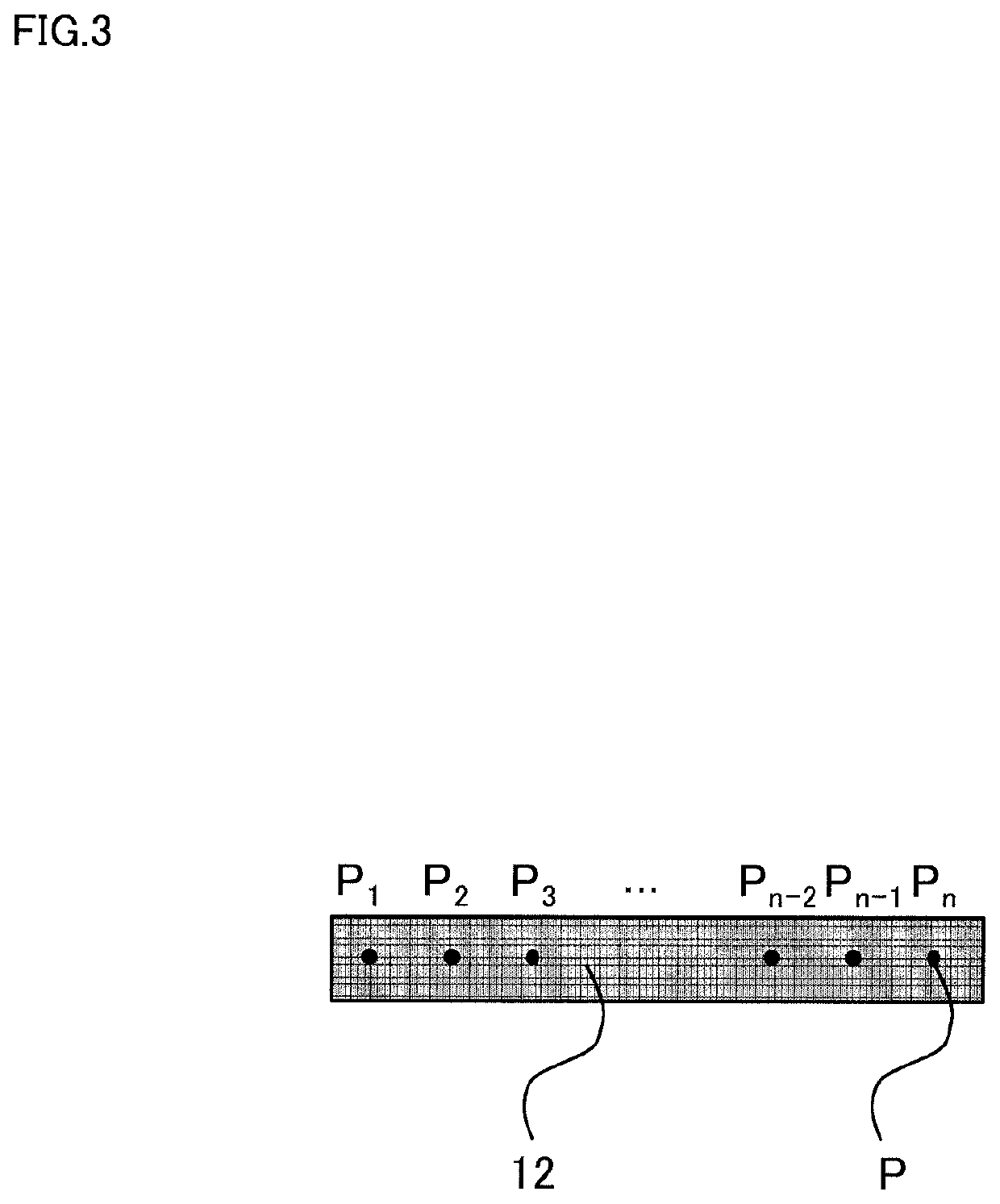
[0027]In the disclosure, as illustrated in FIG. 2, a touch probe 11 is mounted to a main spindle 2a of a spindle head 2, a masterwork 12 as a measurement object is fixed to a table 3, and a position of a target on the masterwork 12 is measured with the touch probe 11. FIG. 2 is an example in which the target on a plane of the masterwork 12 is measured and Z-direction component straightness of an X-axis is measured. The disclosure can be embodied to a case where straightness and positioning accuracy of another axis and another component are measured. Here, a numerical control device disposed in a machine tool functions as an error value acquisition unit, a disturbance inde...


PUM


Abstract

An error measurement method for a machine tool measures an error in a machine tool that includes two or more translational axes, a table, and a spindle head. The error measurement method includes installing a masterwork having a plurality of targets on the table and detecting a position of each of the targets using a sensor mounted to the spindle head to acquire a measured value regarding the position of each of the targets and to acquire an error value regarding the position of each of the targets using each of the acquired measured values and a preliminarily acquired calibration value regarding the position of each of the targets. The error measurement method further includes calculating at least one disturbance index value indicative of a degree of disturbance in the measurement for each of the targets, and determining whether the disturbance index value exceeds a preliminarily set threshold.

Description

BACKGROUND OF THE INVENTION[0001]This application claims the benefit of Japanese Patent Application Number 2019-212622 filed on Nov. 25, 2019, the entirety of which is incorporated by reference.TECHNICAL FIELD OF THE INVENTION[0002]The disclosure relates to a method for measuring an error in a machine tool and the machine tool configured to perform the method.DESCRIPTION OF RELATED ART[0003]FIG. 1 is a schematic diagram of a numerical control machine tool (machining center) having three translational axes.[0004]A spindle head 2 is allowed to perform a motion of two degrees of translational freedom in an X-axis and a Z-axis, which are the translational axes and are orthogonal to one another. A table 3 is allowed to perform a motion of one degree of translational freedom in a Y-axis, which is the translational axis and orthogonal to the X-axis and the Z-axis. Accordingly, the spindle head 2 has three degrees of translational freedom with respect to the table 3. Servomotors, which are ...

Claims


Application Information

Patent Timeline
IPC IPC(8): B23Q15/24B23Q17/22
CPCB23Q17/2233B23Q15/24B23Q2717/00B23Q17/22G05B19/401G05B2219/37581
Inventor KOJIMA, TAKUYAMATSUSHITA, TETSUYA
Owner OKUMA CORP
Why Eureka
Try Eureka