Magnetic encoder and production method therefor

Inactive Publication Date: 2016-02-04
NTN CORP
View PDF0 Cites 4 Cited by
  • Summary
  • Abstract
  • Description
  • Claims
  • Application Information

AI Technical Summary

Benefits of technology

The patent describes a magnetic encoder for a wheel bearing device that uses a plastic magnet with high magnetic force. The plastic magnet is fixed to the inner member of the device using an adhesive and a sealing agent, which prevents rattling and deformation due to temperature changes. The use of the sealing agent allows for a firm fixation without the need for bonding or caulking, reducing manufacturing costs and preventing a decrease in magnetic properties. The plastic magnet is made of a thermoplastic resin and magnetic powder, which reduces the difference in expansion and shrinkage between the magnet and the core metal, further reducing the load on the magnet. The magnetic encoder is used in a wheel bearing device and is fitted in a press-fitted fashion to the inner member of the device.

Problems solved by technology

However, an increase in cost caused by performing the surface roughening is unavoidable.
In addition, liquid management and an application process of an adhesive themselves are costly work processes.
However, an increase in cost caused by performing the baking treatment is also unavoidable in this method.
In a configuration in which a plastic magnet and a core metal are integrally molded by insert-molding, after the integral molding, a slight gap (backlash) occurs between the plastic magnet and the core metal due to mold shrinkage of the plastic magnet.
There is also a problem in that when the plastic magnet moves even slightly due to the backlash, the magnetic accuracy deteriorates.
Therefore, when the inner peripheral surface and the outer peripheral surface of the multipolar magnet are caulked by the core metal as in Patent Document 3, if the multipolar magnet expands, in particular, in a high-temperature environment, there is the possibility that the expansion cannot be released to any of the inner peripheral surface and the outer peripheral surface of the multipolar magnet, so that, for example, the multipolar magnet deforms, leading to a decrease in the accuracy of rotation detection.

Method used


Image

  • Magnetic encoder and production method therefor
  • Magnetic encoder and production method therefor
  • Magnetic encoder and production method therefor

Examples


first embodiment

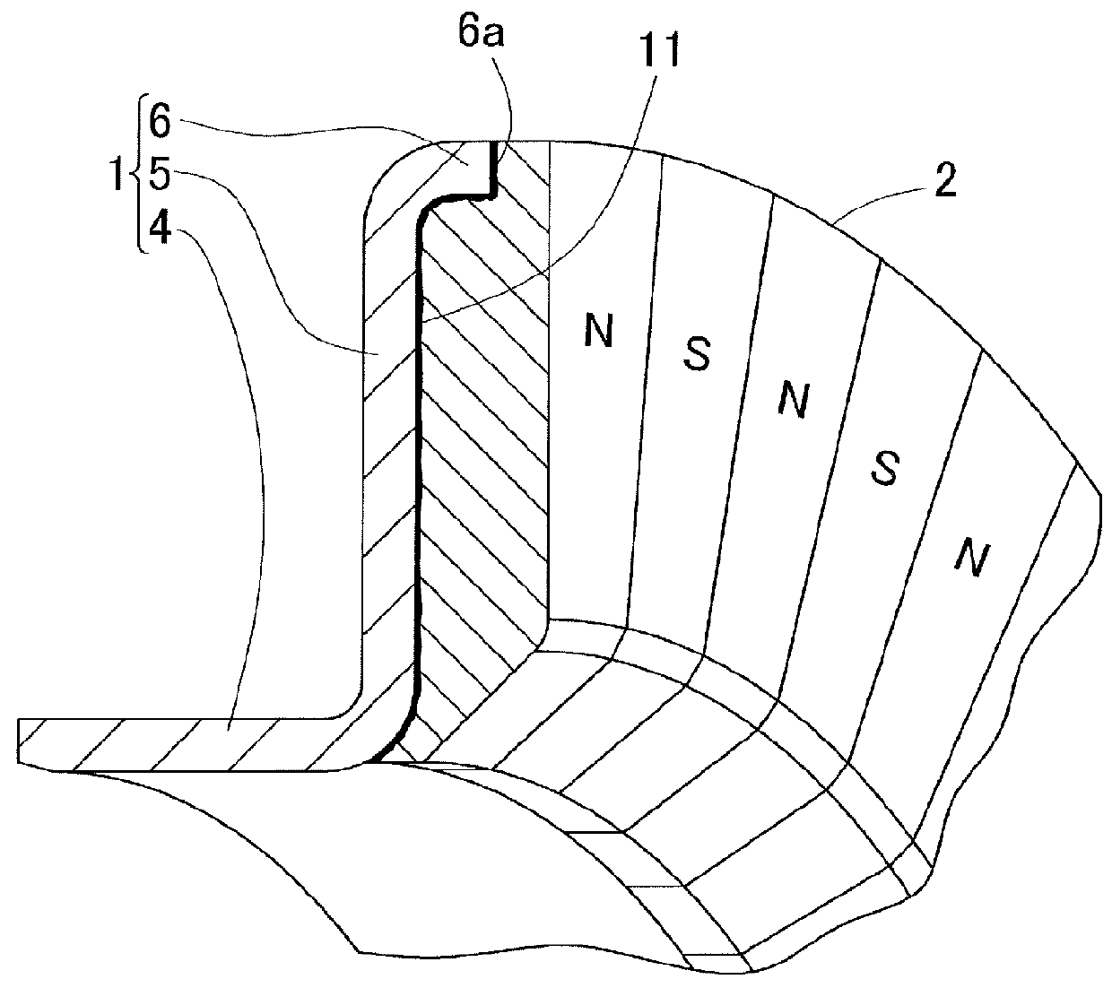
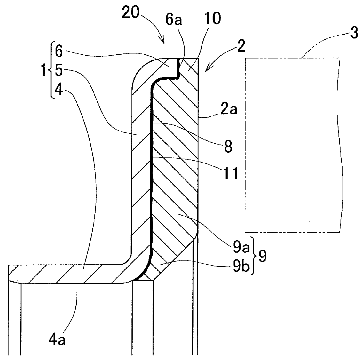
[0065]A magnetic encoder according to the present invention will be described with reference to FIGS. 1 to 7. The following description also includes a description of a production method for the magnetic encoder. As shown in FIGS. 1 and 2, a magnetic encoder 20 includes an annular core metal 1 and a multipolar magnet 2 provided on the core metal 1. A minute gap defined between the core metal 1 and the multipolar magnet 2 is filled with a sealing agent 11. In the multipolar magnet 2, magnetic poles N and S are formed alternately in a circumferential direction. The magnetic encoder 20 is attached to a rotating member which is not shown, and a magnetic sensor 3 is opposed to the multipolar magnet 2. In this state, the magnetic encoder 20 is used for rotation detection.

[0066]The core metal 1 is formed of a metal steel plate of a magnetic material, in particular, a ferromagnetic material, for example, a ferrite-based stainless steel plate (SUS430 which complies with JIS), a cold rolled s...

second embodiment

[0090]In the second embodiment, after the staking portions 7 are provided, the multipolar magnet 2 is integrally molded on the annular portion 8, made up of the upright plate portion 5 and the outer diameter cylindrical portion 6 of the core metal 1, by insert-molding. After the insert-molding, the gap between the core metal 1 and the multipolar magnet 2 is filled with the sealing agent 11. Of the multipolar magnet 2 provided on the annular portion 8 of the core metal 1, a surface 2a confronting the magnetic sensor 3 continues from the axial end of the outer diameter cylindrical portion 6 so as to be flush therewith. The multipolar magnet 2 is formed such that the axial thickness t1 thereof is larger than that of the conventional multipolar magnet.

[0091]The thermal durability test will be described. In each of Examples 1 to 7 of a magnetic encoder in which only the staking portions 7 are provided and the sealing agent 11 is not used in the second embodiment and Comparative Examples ...

third embodiment

[0109]In the third embodiment, in insert-molding, for example, as shown in FIG. 17A, the magnet material is loaded into the cavity through gates 23 at locations corresponding to the respective magnetic poles S and N. Thus, the magnet material loaded through each gate 23 collides against each other at the boundary between a portion that is to be the magnetic pole S and a portion that is to be the magnetic pole N, to form a weld 24 at the boundary. Since the welds 24 are formed, when the multipolar magnet 2 is magnetized later, a magnetic force reduction due to canceling between the magnetic poles S and N adjacent to each other is suppressed. In other words, the weld 24 serves as the magnetic force reduction suppression section which suppresses a magnetic force reduction due to canceling between the magnetic poles S and N adjacent to each other. Thereafter, as shown in FIG. 17B, the gates 23 are removed, and magnetization is performed. In FIGS. 17A and 17B and FIGS. 18 to 20 described...


PUM

PropertyMeasurementUnit
Diameteraaaaaaaaaa
Magnetic fieldaaaaaaaaaa
Magnetismaaaaaaaaaa

Abstract

A magnetic encoder is a magnetic encoder including a core metal and a multipolar magnet provided on the core metal and having magnetic poles formed alternately in a circumferential direction. The core metal includes an inner diameter cylindrical portion, an upright plate portion extending from one end of the inner diameter cylindrical portion toward an outer diameter side, and an outer diameter cylindrical portion extending axially from an outer diameter side end of the upright plate portion; the multipolar magnet is integrally molded on an annular portion, of the core metal, extending over the upright plate portion and the outer diameter cylindrical portion, by insert-molding such that an end surface of the outer diameter cylindrical portion is embedded; and a gap between the core metal and the multipolar magnet is filled with a sealing agent.

Description

CROSS REFERENCE TO THE RELATED APPLICATION[0001]This application is a continuation application, under 35 U.S.C. §111(a), of international application No. PCT / JP2014 / 059987, filed Apr. 4, 2014, which claims priority to Japanese patent application No. 2013-081086, filed Apr. 9, 2013, Japanese patent application No. 2014-016788, filed Jan. 31, 2014, and Japanese patent application No. 2014-016789, filed Jan. 31, 2014, the disclosure of which are incorporated by reference in their entirety into this application.BACKGROUND OF THE INVENTION[0002]1. Field of the Invention[0003]The present invention relates to a magnetic encoder which is mounted to a bearing or the like and functions for rotation speed detection, and a production method therefor.[0004]2. Description of Related Art[0005]A magnetic encoder is incorporated into, for example, a wheel bearing device of a vehicle and is used as a rotation detection device which detects a rotation speed of a wheel at an anti-lock braking system (A...

Claims


Application Information

Patent Timeline
IPC IPC(8): G01D5/12G01P3/44
CPCG01P3/443G01D5/12G01D5/2451F16C33/723F16C41/007F16C19/184F16C2326/02G01D2205/80
Inventor HARANO, TAKUJIUEMOTO, LKUOMIYAZAKI, SHINJIODA, TAKAYUKINODA, HIROYUKI
Owner NTN CORP
Why Eureka
Try Eureka