Method and device for determining a visual impairment of a camera

a technology for visual impairment and camera, applied in the field of methods and devices for determining visual impairment of cameras, can solve problems such as loss of efficiency, validation of image analyses, local distortions and/or partially blocked light paths, and/or false color renderings

Active Publication Date: 2022-11-22
ROBERT BOSCH GMBH
View PDF7 Cites 0 Cited by
  • Summary
  • Abstract
  • Description
  • Claims
  • Application Information

AI Technical Summary

Benefits of technology

[0006]In accordance with an example embodiment of the present invention, a method according to the present invention advantageously enables the determination of a visual impairment of a camera when viewing through a window. With this example method, it is advantageously possible to ensure a positive result quality in the image evaluation of the camera. This is made possible according to the present invention by the features described herein. Additional embodiments of the present invention are described herein.
[0008]This is understood to mean, for example, that the illumination is controlled in such a way that it is not detected by the driver. The control and the position and design of the illumination are accordingly also coordinated with each other in such a way that the illumination is not detected by the driver. In this way, it is possible to avoid a blinding of the driver and as a result to optimize the safety as well as the comfort. While a “control” of the illumination is described within the scope of the present invention, a “regulation” of the illumination is, of course, also encompassed by the present invention. In addition, the driver, in particular, is mentioned, the embodiment in this case may also refer to the driver of the vehicle as well as to any vehicle occupant.
[0034]With this embodiment variant of the present invention in the form of a device as well, the object of the present invention may be achieved advantageously and with high validity. Thus, a device may be considered to be: a camera and / or an illumination device and / or a windshield wiper, in particular, a windshield wiper that includes an integrated illumination device.
[0036]In one advantageous specific embodiment of the present invention, the device is positioned at least partially on the outside of the window. This is understood to mean that at least parts of the device are positioned on the outside of the window. The outside of the window is understood, for example, to mean the area of the windshield, which is directed toward the surroundings of the motor vehicle and not toward the interior of the motor vehicle. A very exact ascertainment of visual impairments on the outside of the window may thereby advantageously take place. The illumination device is positioned, for example, for illumination on the outside of the windshield. As a result, the illumination of the windshield also takes place on the outside. Since scratches and stone damage occur, in particular, on the outside of the window, it is possible to validly identify the defects via an incident light illumination from outside.

Problems solved by technology

A degradation of the windshield in this case may result in a loss of efficiency, in particular, in the validation of the image analyses.
A degradation may result, for example, due to damage to the windshield, (scratches, stone damage, etc.) or to any change in the spectral transparency of the windshield.
A degradation in this case results in local distortions and / or in partially blocked light paths and / or in false color renderings.
This results in a false representation of the surroundings of the vehicle in the image data.
This may result in erroneous analysis results.
Such structures may be damage to the window.
This may be mechanical damage, cracks or stone damage, for example.
However, this light is not fully reflected at damage or other structural features of the window, but is partly decoupled.

Method used


Image

  • Method and device for determining a visual impairment of a camera
  • Method and device for determining a visual impairment of a camera
  • Method and device for determining a visual impairment of a camera

Examples


Embodiment Construction

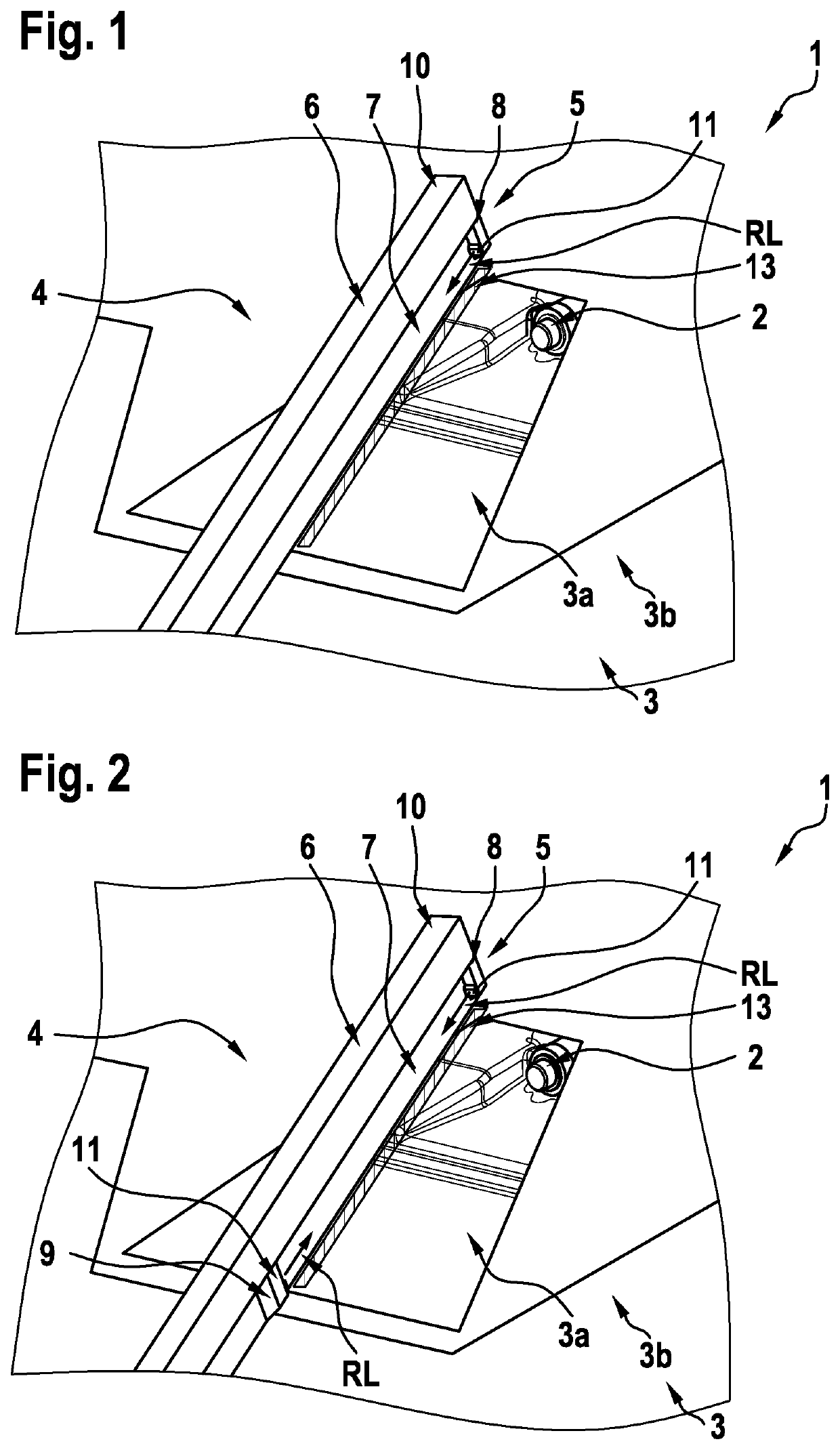
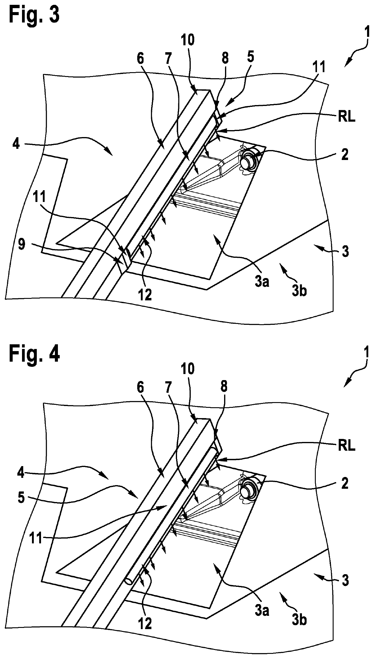
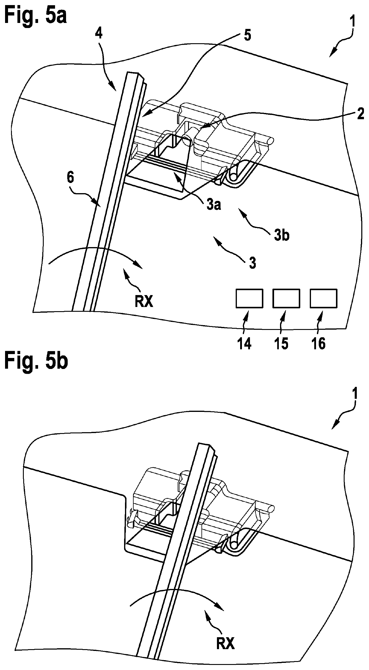
[0056]FIG. 1 shows a device according to a first specific embodiment of the present invention. Shown here is a camera 2 as well as a window 3 of a motor vehicle 1 not shown. The window 3 includes a non-transparent overprint 4, a so-called blackprint. The remaining area of the window 3 may be defined as the driver viewing area 3b. Blackprint 4 leaves an area blank, viewing area 3a for the camera. This camera viewing area 3a is also not visible to the driver, since it is covered by the camera module mounted on the inside of the window. A windshield wiper 6 is also shown, which includes an illuminating device 5. Windshield wiper 6 also includes, of course, a windshield wiper blade 7. Windshield wiper 6 includes a back web 10, as well as an end web 8. Illumination device 5 includes a light source 11. Light source 11 is integrated into end web 8. Light source 11 is designed, in particular, as an LED light emitter. Light sources 11 radiate in illumination direction RL and illuminate an il...


PUM


Abstract

A method for determining a structural image of a window of a motor vehicle with the aid of a camera, the window separating the camera from surroundings of the motor vehicle. The method includes a highlighting of image structures present in the structural image with the aid of an illumination of the window, the image structures being suitable for ascertaining a visual impairment of a view of the camera through the window. The illumination is configured in such a way that it is not detected by a driver. A device for implementing the method is also provided.

Description

CROSS REFERENCE[0001]The present application claims the benefit under 35 U.S.C. § 119 of German Patent Application No. DE 102019218450.2 filed on Nov. 28, 2019, which is expressly incorporated herein by reference in its entirety.BRIEF SUMMARY[0002]The present invention relates to a method for determining a structural image of a window of a motor vehicle with the aid of a camera, the window separating the camera from surroundings of the motor vehicle, the method is characterized in that a highlighting of the image structures present in the structural image takes place with the aid of an illumination of the window, the image structures being suitable for ascertaining a visual impairment of a view of the camera through the window, and the illumination being configured in such a way that it is not detected by a driver. According to the present invention, a device for implementing the method is also provided.BACKGROUND INFORMATION[0003]Modern motor vehicles frequently have a camera for d...

Claims


Application Information

Patent Timeline
Patent Type & Authority Patents(United States)
IPC IPC(8): H04N7/18G06T7/00H04N5/225
CPCH04N7/18G06T7/0002H04N5/2256G06T2207/30252G06V20/56G06V10/141H04N7/183H04N23/56H04N23/57
Inventor BAKI, MIHÁLY DEZSÕVARGA-UMBRICH, KAROLY
Owner ROBERT BOSCH GMBH
Why Eureka
Try Eureka