Supercharge Your Innovation With Domain-Expert AI Agents!

Connector

a technology of connecting rods and connectors, applied in the direction of vehicle connectors, coupling device connections, electrical apparatus, etc., can solve the problems of large number of components and poor operability

Inactive Publication Date: 2001-07-12
SUMITOMO WIRING SYST LTD
View PDF0 Cites 6 Cited by
  • Summary
  • Abstract
  • Description
  • Claims
  • Application Information

AI Technical Summary

Problems solved by technology

Consequently, there is a problem that the number of components is large.
Furthermore, separate operations are required to push in the fitting detecting member 105 and the short-circuiting member 106, and operability is consequently poor.

Method used


Image

  • Connector
  • Connector
  • Connector

Examples


Embodiment Construction

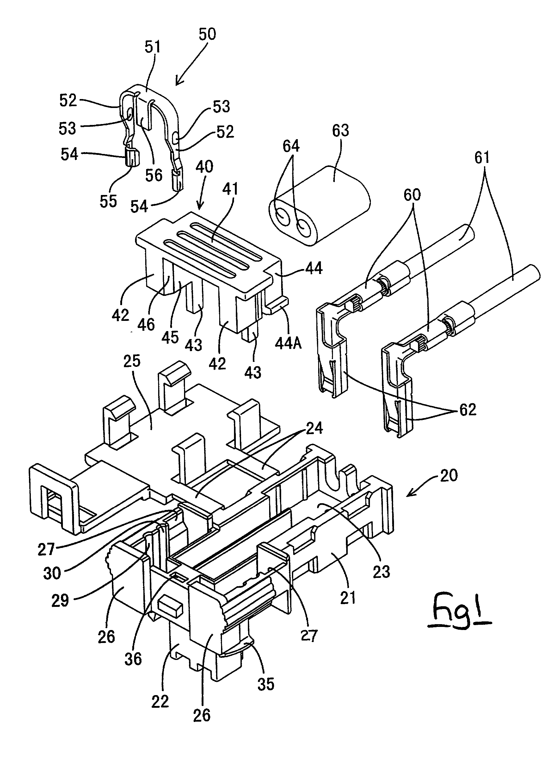
[0027] A connector of the present embodiment is provided with a male housing 10 and a female housing 20, these two housings 10 and 20 being capable of fitting mutually together and of being separated.

[0028] The male housing 10 is made from plastic. As shown in FIGS. 13 and 14, this male housing 10 has a recess 11 opening onto its upper face. A left and right pair of upwardly protruding male terminal fittings 12 (the terminal fittings of the present invention) and a shorting terminal 13 are housed within this recess 11. The shorting terminal 13 has a pair of resilient contacts 14 capable of making resilient contact with the side with the male terminal fittings 12. When the two housings 10 and 20 are in a separated state, the pair of resilient contacts 14 make contact with the pair of male terminal fittings 12, causing a short-circuiting state therebetween. Furthermore, as will be explained, when the two housings 10 and 20 are fitted together, the resilient contacts 14 are bent by a s...


PUM


Abstract

The invention provides an electrical connector with a reduced number of components and improved operability. As a fitting detecting member 40 is moved from a detecting position to a waiting position, releasing members 52 of a short-circuit releasing member 50 return, due to their own resilient returning force, from a short-circuit releasing position to a position allowing short-circuiting to occur. A separate means is not required to return the releasing members 52 to the position allowing short-circuiting to occur. Consequently, the number of components required is reduced. After two housings 10 and 20 have been fitted together, moving the fitting detecting member 40 from the waiting position to the detecting position pushes the releasing members 52 from the position allowing short-circuiting to occur to the short-circuit releasing position. That is, both the detecting operation of the fitting detecting member 40 and the short-circuit releasing operation of the short-circuit releasing member 50 are performed with a single action, thereby improving operability.

Description

[0001] The present invention relates to an electrical connector.BACKGROUND TO THE INVENTION[0002] JP 11-149958 describes a connector provided with a function for detecting the fitted state of connector housings and capable of releasing a short-circuiting state of terminal fittings of a first connector housing by means of a short-circuit releasing member provided on a second connector housing.[0003] As shown in FIGS. 15 and 16 of this specification, when two housings 101 and 102 are in separated state, terminal fittings 103 of the first housing 101 are short-circuited by shorting terminals 104, and a fitting detecting member 105 and a short-circuit releasing member 106 are attached to the second housing 102 in a temporarily retained state. When attachment is to take place, the two housings 101 and 102 are first fitted together. Next, the short-circuit releasing member 106 is pushed in towards a return spring 107, thereby releasing the short-circuiting state. Finally, the fitting dete...

Claims


Application Information

Patent Timeline
IPC IPC(8): H01R13/639H01R31/08
CPCH01R13/639H01R2201/26
Inventor NIMURA, KAZUHIKO
Owner SUMITOMO WIRING SYST LTD
Features
  • R&D
  • Intellectual Property
  • Life Sciences
  • Materials
  • Tech Scout
  • Unparalleled Data Quality
  • Higher Quality Content
  • 60% Fewer Hallucinations
Learn More