Encoded device for a toner cartridge

a toner cartridge and encoder technology, applied in the field of encoder devices for toner cartridges, can solve the problems of inability to effectively measure the amount of unused toner remaining, lack of accuracy in consumption counts, and limited information that can be provided to the machin

Inactive Publication Date: 2001-11-01
LEXMARK INT INC
View PDF0 Cites 21 Cited by
  • Summary
  • Abstract
  • Description
  • Claims
  • Application Information

AI Technical Summary

Problems solved by technology

While this method is effective, the amount of information that can be provided to the machine is limited.
Therefore at best, the consumption count lacks accuracy.
Few methods or apparatus effectively measure the amount of unused toner remaining.
However, when loaded the paddle lags the driving member by an angular distance that increases with increasing load.

Method used


Image

  • Encoded device for a toner cartridge
  • Encoded device for a toner cartridge
  • Encoded device for a toner cartridge

Examples


Embodiment Construction

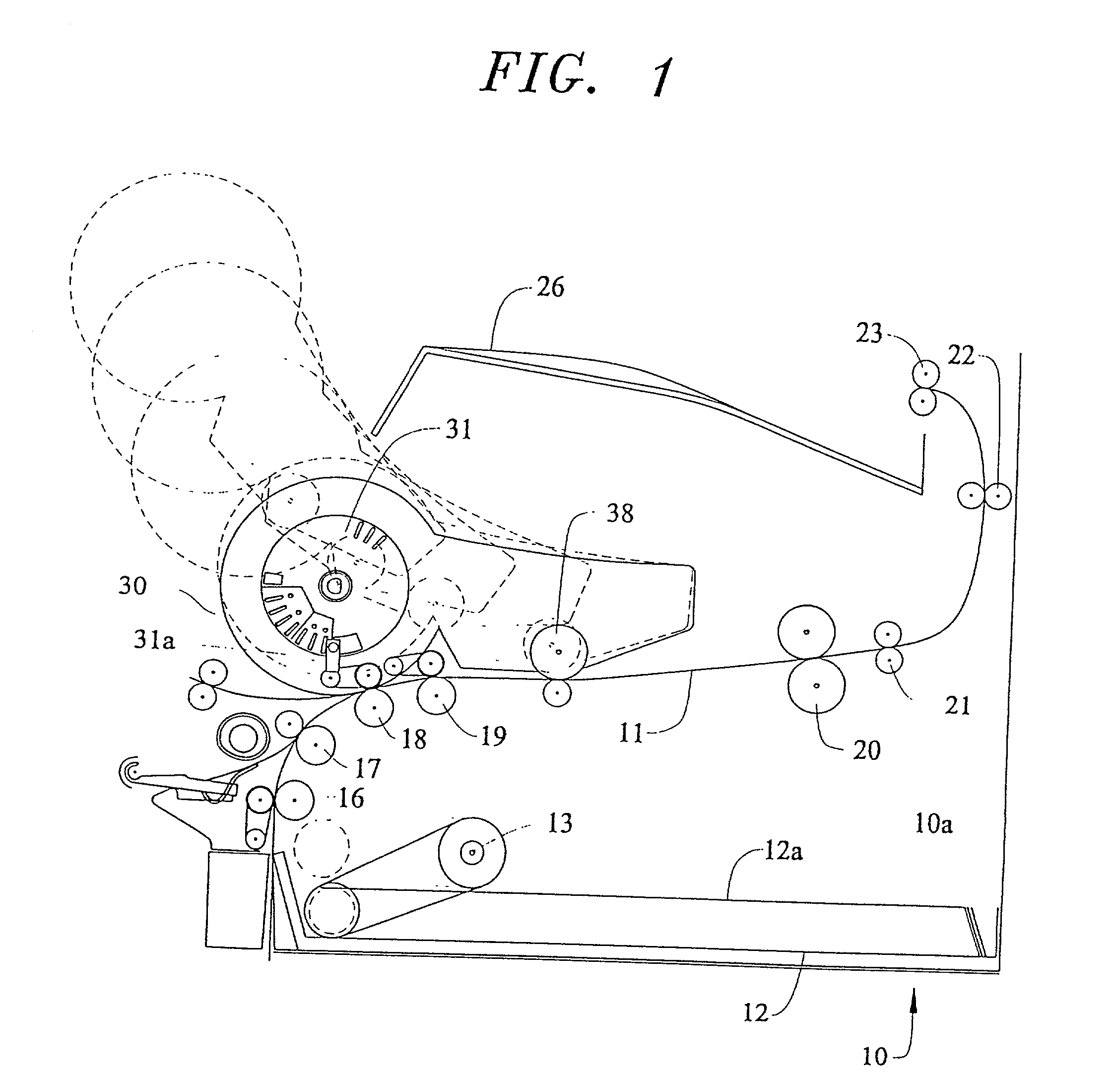
[0042] Turning now to the drawings, and particularly FIG. 1 thereof, a laser printer 10 constructed in accordance with the present invention, is illlustrated therein. FIG. 1 shows a schematic side view of the printer 10, illustrating the print receiving media path 11 and including a replacement supply electrophotographic (EP) cartridge 30, constructed in accordance with the present invention. As illustrated, the machine 10 includes a casing or housing 10a which supports at least one media supply tray 12, which by way of a picker arm 13 feeds cut sheet of print receiving media 12a (e.g., paper) into the media path 11 past the print engine which forms in the present instance part of the cartridge 30 and through the machine 10. A transport motor dirve assembly 15 (FIG. 3) affords the driving action for feeding the media through and between the nips of pinch roller pairs 16-23 into a media receiving output tray 26.

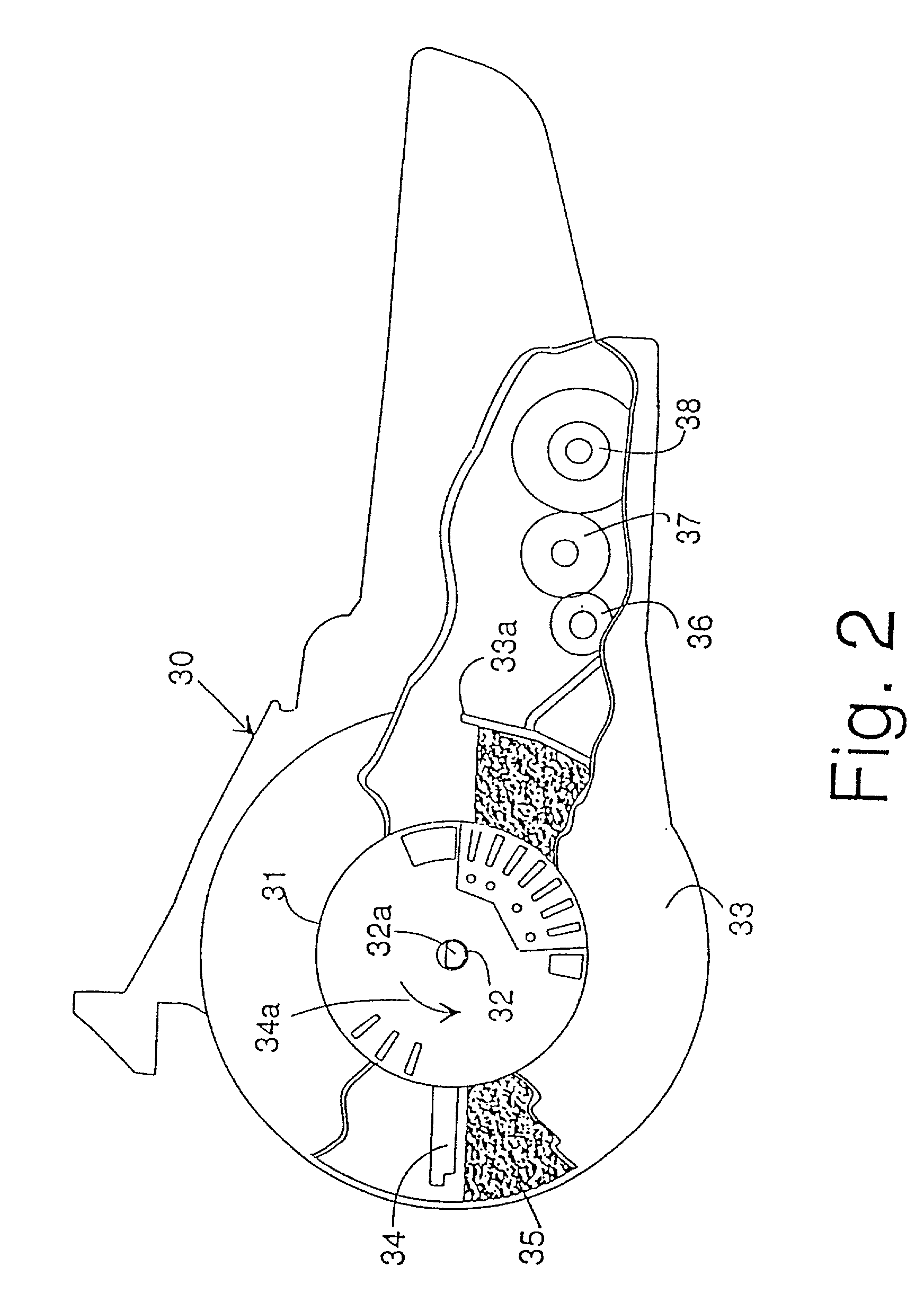
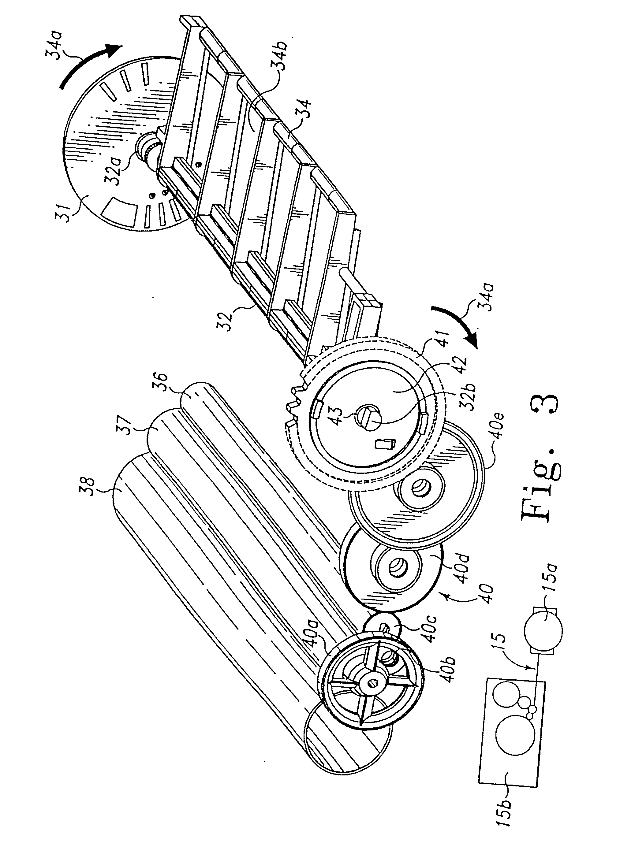
[0043] In accordance with the invention, and referring now to FIGS. 1 & 2...


PUM


Abstract

One aspect of the invention is the invention is directed to a toner cartridge including a sump for carrying a supply of toner. An agitator is rotatably mounted in the sump, and the agitator has a first end and a second end. An encoded wheel is coupled to the first end of the agitator. The encoder wheel is structured and adapted to include a first preselected cartridge characteristic indicia having a first extent, a stop indicia having a second extent larger than the first extent and a start indicia having a third extent larger than the second extent. Each indicia may be in the form of a slot. Preferably, the start indicia is positioned between about a 5:00 o'clock position and a 6:00 O'clock postition. The stop indicia is positioned at about a 9:00 o'clock position. At least one preselected cartridge characteristic indicia is positioned between the start indicia and the stop indicia. At least one measurement indicia is located between about 200 degrees and about 230 degrees in a clockwise direction from the 6:00 o'clock position.

Description

[0001] This application is a continuation of U.S. Pat. application Ser. No. 08 / 975,389 filed on Nov. 20, 1997, which is a continuation of U.S. Pat. application Ser. No. 08 / 768,257 filed on Dec. 17, 1996, which is a continuation-in-part of U.S. Pat. application Ser. No. 08 / 602,648 filed on Feb. 16, 1996, now U.S. Pat. No. 5,634.169.[0002] A portion of the disclosure of this patent document contains material which is subject to copyright protection. The copyright owner has no objection to the facsimile reproduction by anyone of the patent document or the patent disclosure, as it appears in the Patent and Trademark Office patent file or records, but otherwise reserves all copyright rights whatsoever.[0003] 1. Field of the Invention[0004] The present invention relates to Electrophotographiic (EP) machines and more particularly relates to methods and apparatus associated witih replaceable supply cartridges for such machines wherein information concerning thle cairtridge is provided to th...

Claims


Application Information

Patent Timeline
Patent Type & Authority Applications(United States)
IPC IPC(8): G03G15/08G03G21/18
CPCG03G15/0822G03G15/0896G03G21/1896G03G15/0889G03G15/0856G03G15/0858G03G2221/1838
Inventor CURRY, STEVEN ALANNEWMAN, BENJAMIN KEITHWARD, EARL DAWSON IIWRIGHT, PHILLIP BYRON
Owner LEXMARK INT INC
Why Eureka
Try Eureka