

Optical disk, optical disk apparatus, and method for writing figures
a technology of optical disk and optical disk, which is applied in the direction of optical recording/reproducing/erasing methods, recording apparatuses, instruments, etc., can solve the problems of inability to rewrite and the content the user has recorded on the optical disk cannot be confirmed
- Summary
- Abstract
- Description
- Claims
- Application Information
AI Technical Summary
Problems solved by technology
Method used
Image

Examples
Embodiment Construction
[0054] In what follows, the mode of carrying out the invention will be explained with reference to the drawings.
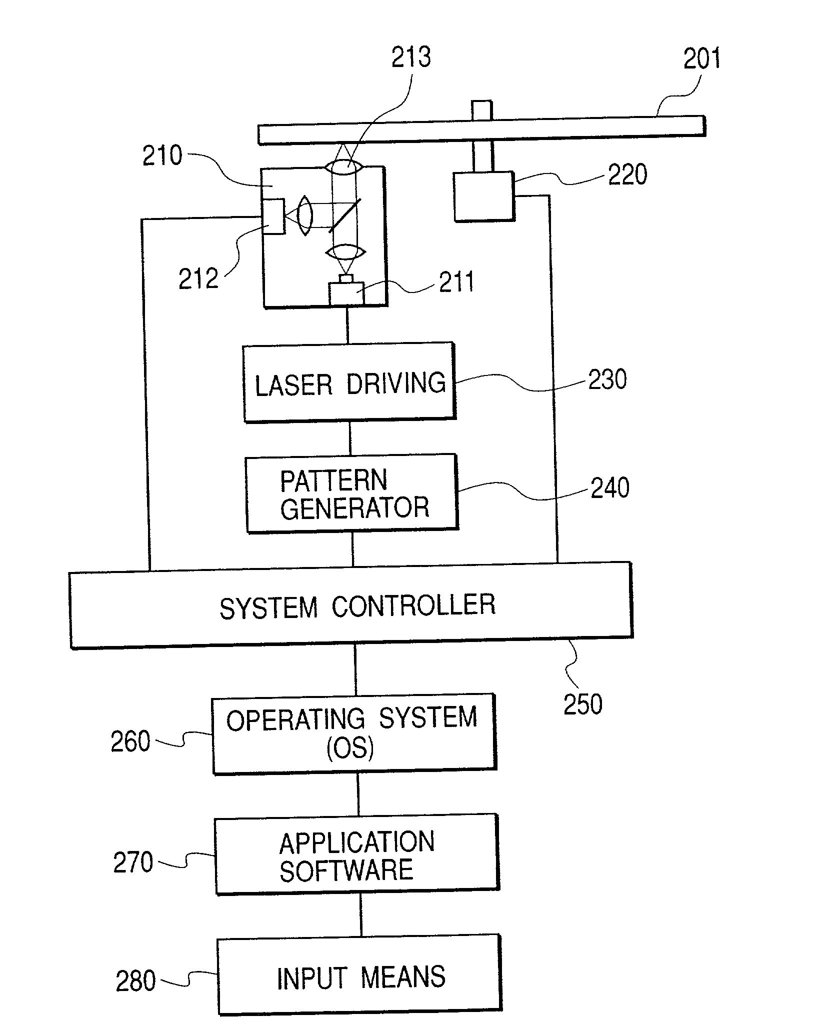
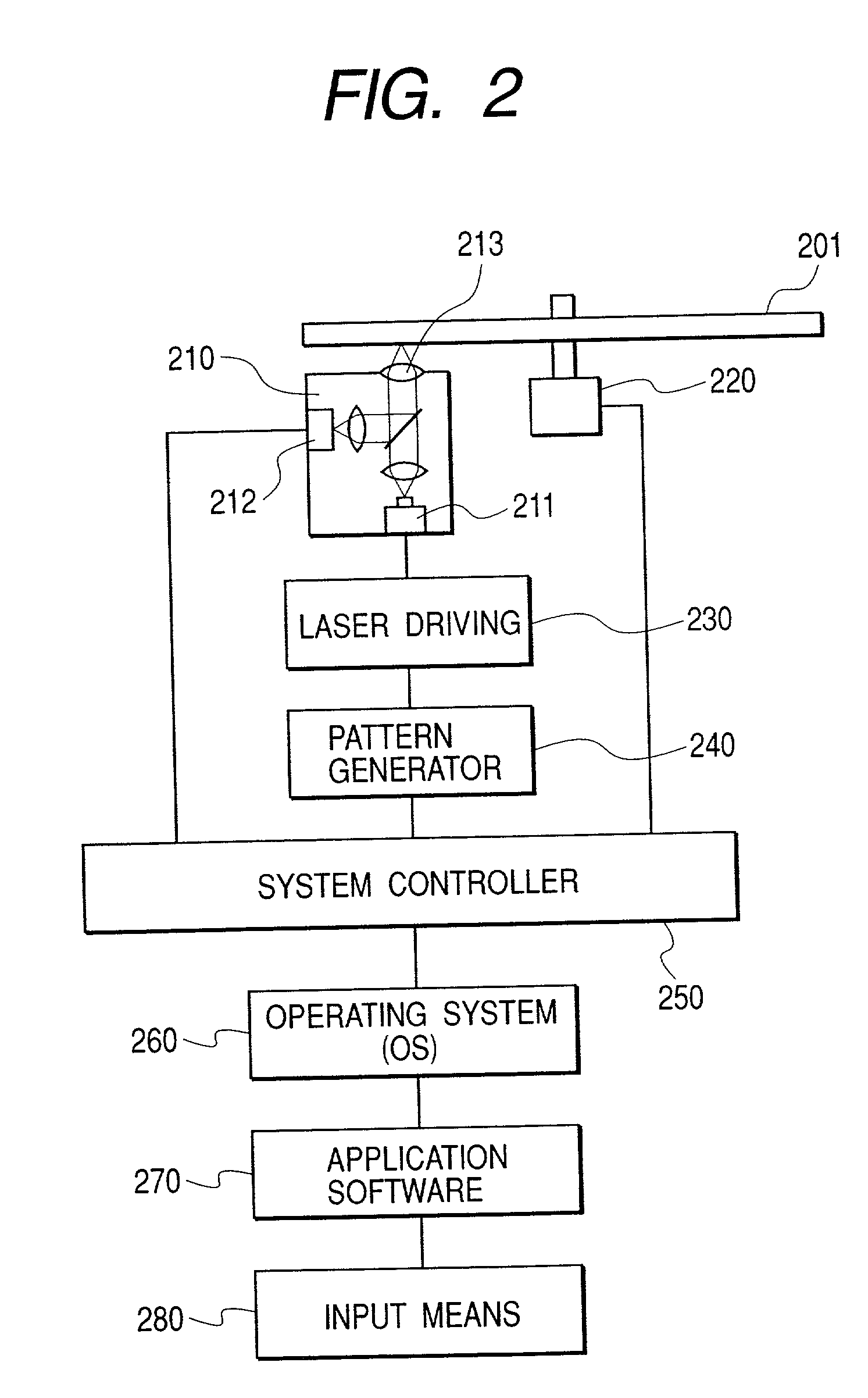
[0055] FIG. 2 is a schematic block diagram showing one example of the optical disk apparatus having a function of writing figures according to the present invention. Incidentally, for the convenience of explanation, how the optical disk 201 is mounted on the apparatus is shown. Although the optical disk 201 is essential to write information, the optical disk 201 is dismounted from and mounted on the optical disk apparatus according to need. The optical disk apparatus is constructed of a semiconductor laser 211, an optical head 210 which is capable of moving in the radial direction of the optical disk 201 and is provided with a photodetector 212 and an object lens 213, a motor 220 which turns and drives the optical disk 201, a laser driver 230 which drives the semiconductor laser 211 according to the pattern generated by a pattern generating circuit 240, a system controller...
PUM
 Abstract
Description
Claims
Application Information