Method for utilizing temperature to determine a battery state

Inactive Publication Date: 2008-03-25
LINVATEC
View PDF11 Cites 1102 Cited by
  • Summary
  • Abstract
  • Description
  • Claims
  • Application Information

AI Technical Summary

Benefits of technology

[0012]One advantage of a method according to the invention is that it is independent of the type of battery under test. Another advantage is that the method is very ef

Problems solved by technology

Regardless of battery form or application, battery quality tends to diminish over time.
Quite often, batteries will remain idle for long periods of time before a demand for battery power arises.
However, measurements taken under load conditions are known to introduce uncertainty due resistive effects from test leads, contacts, and internal components of the battery.
One drawback, however, is that this method fails to

Method used


Image

  • Method for utilizing temperature to determine a battery state
  • Method for utilizing temperature to determine a battery state
  • Method for utilizing temperature to determine a battery state

Examples


Example

[0028]As utilized herein, terms such as “about” and “substantially” and “nearly” are intended to allow some leeway in mathematical exactness to account for tolerances that are acceptable in the trade. Accordingly, any deviations upward or downward from the value modified by the terms such as “about” or “substantially” or “nearly” in the range of 1% to 25% or less should be considered to be explicitly within the scope of the stated value. Also herein, the term “battery” refers both to a single battery and to multiple batteries electrically coupled within a single bank or battery pack.

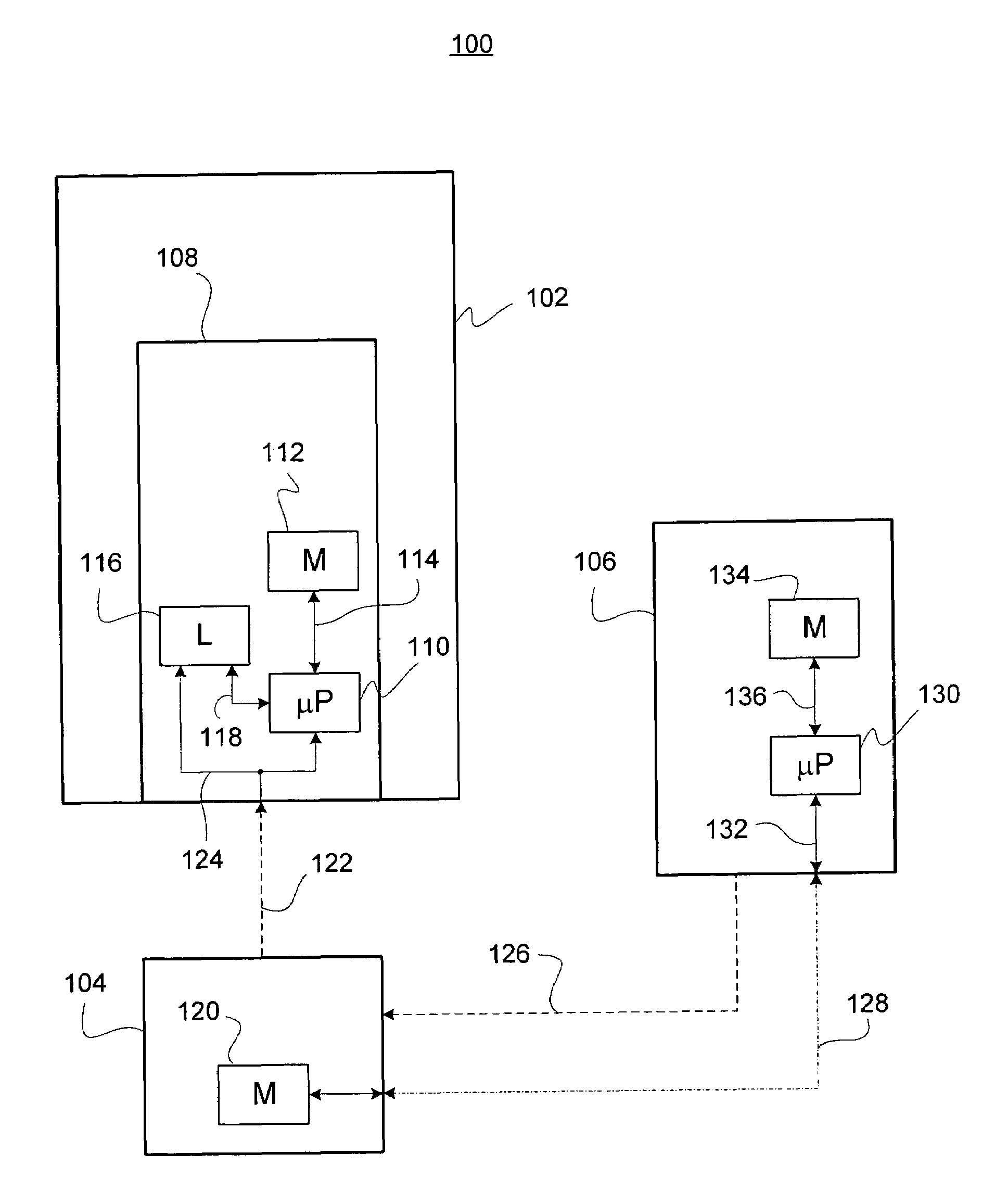
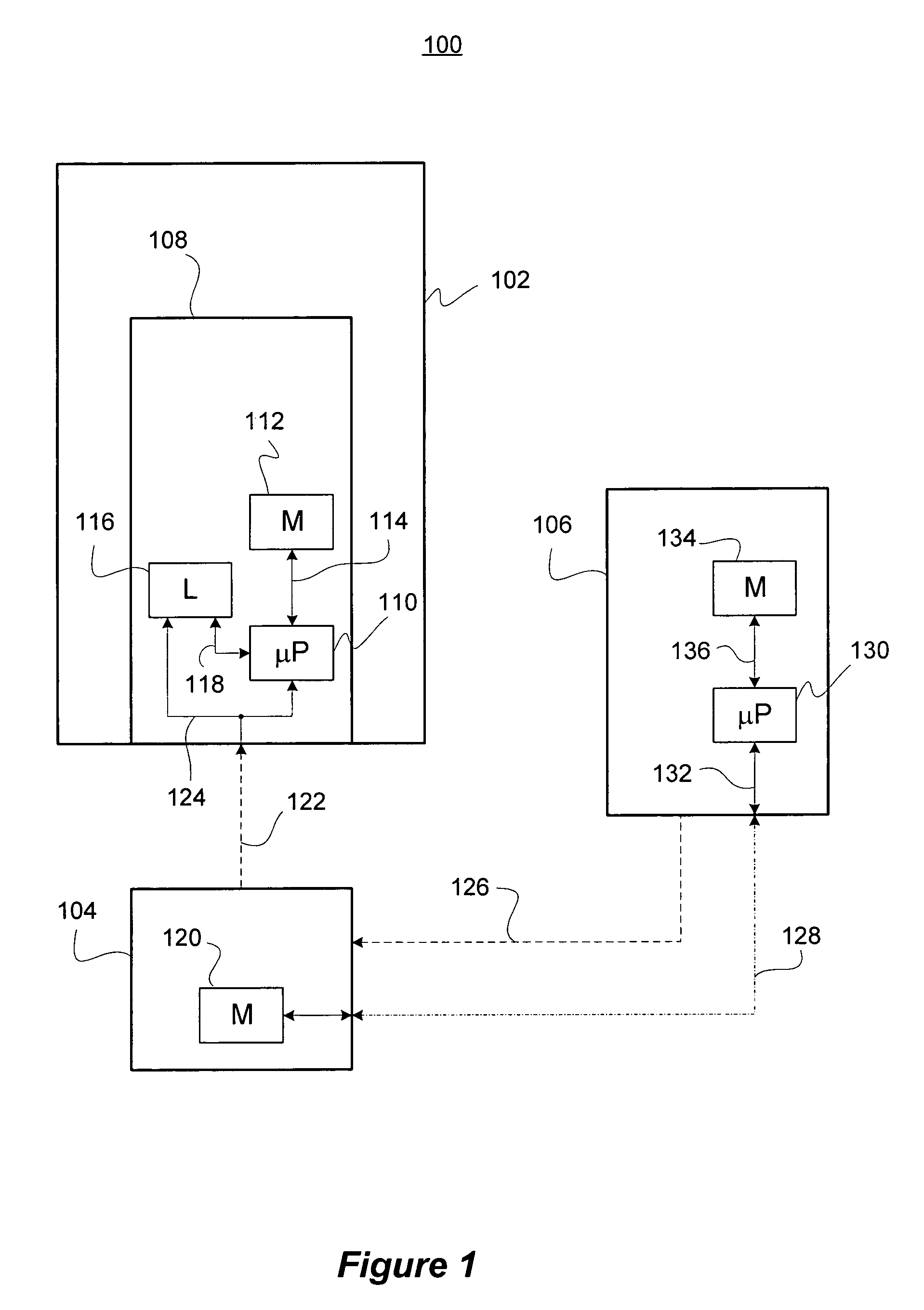
[0029]In one or more embodiments, the present invention may be incorporated within a battery charging system, or within another system that uses as a power source one or more batteries charged by the battery charging system. FIG. 1 illustrates an exemplary system 100 comprising an appliance 102, a battery pack 104, and a battery charging system 106. Appliance 102 may be any device that operates on batter...


PUM


Abstract

A method for determining the state of a battery, or battery pack, that is independent of the type of battery technology under test. The method employs one or more charging and discharging cycles, and measures one or more parameters of battery voltage, temperature, charging time, and charging cycle counts to produce a test value that is compared to empirical data. Based on the comparison, the state is determined, for example, on a pass/fail basis. The method may be embodied as instructions stored in memory and implemented by means of a microprocessor coupled to the memory. In another embodiment, the empirical data is stored within another memory located internal to the battery pack under test.

Description

[0001]This application claims the benefit of U.S. Provisional Application No. 60 / 435,888 filed Dec. 20, 2002, U.S. Provisional Application No. 60 / 435,937 filed Dec. 20, 2002, and U.S. Provisional Application No. 60 / 435,965 filed Dec. 20, 2002, each of which is hereby incorporated by reference herein as though set forth in full.[0002]This application is related to U.S. patent application Ser. No. 10 / 745,337, entitled “Microprocessor Controlled Battery Charger,” filed concurrently herewith, and U.S. patent application Ser. No. 10 / 745,338, entitled “Microprocessor Based Surgical Handpiece,” filed concurrently herewith, each of which is incorporated by reference herein as though set forth in full.BACKGROUND OF THE INVENTION[0003]1. Field of the Invention[0004]The present invention is a method for determining the state of a battery or batteries that form a battery pack. This invention has general applications in battery charging or battery evaluation systems. More specifically, this inve...

Claims


Application Information

Patent Timeline
IPC IPC(8): H01M10/44
CPCG01R31/3631H01M10/443G01R31/3679G01R31/3648G01R31/386G01R31/392Y02E60/10
Inventor REINHART, RONALD R.JENKINS, FREDERICK M.RAVER, JAMES M.NGUYEN, THONG L.SCHAEFER, MARTIN A.
Owner LINVATEC
Why Eureka
Try Eureka