Adjustable illuminators and methods for photodynamic therapy and diagnosis

Active Publication Date: 2017-08-03
DUSA PHARMA INC
View PDF17 Cites 23 Cited by
  • Summary
  • Abstract
  • Description
  • Claims
  • Application Information

AI Technical Summary

Benefits of technology

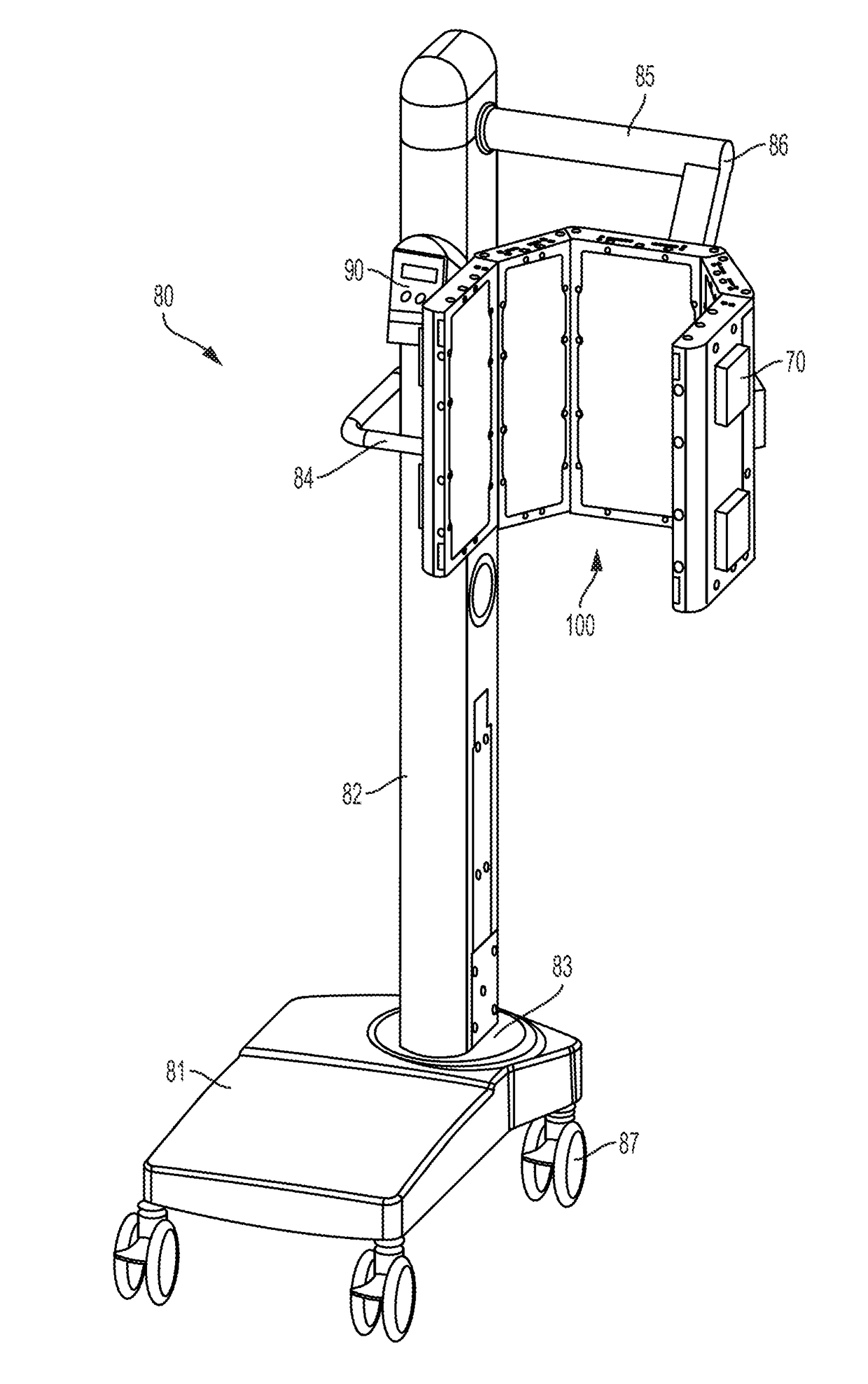
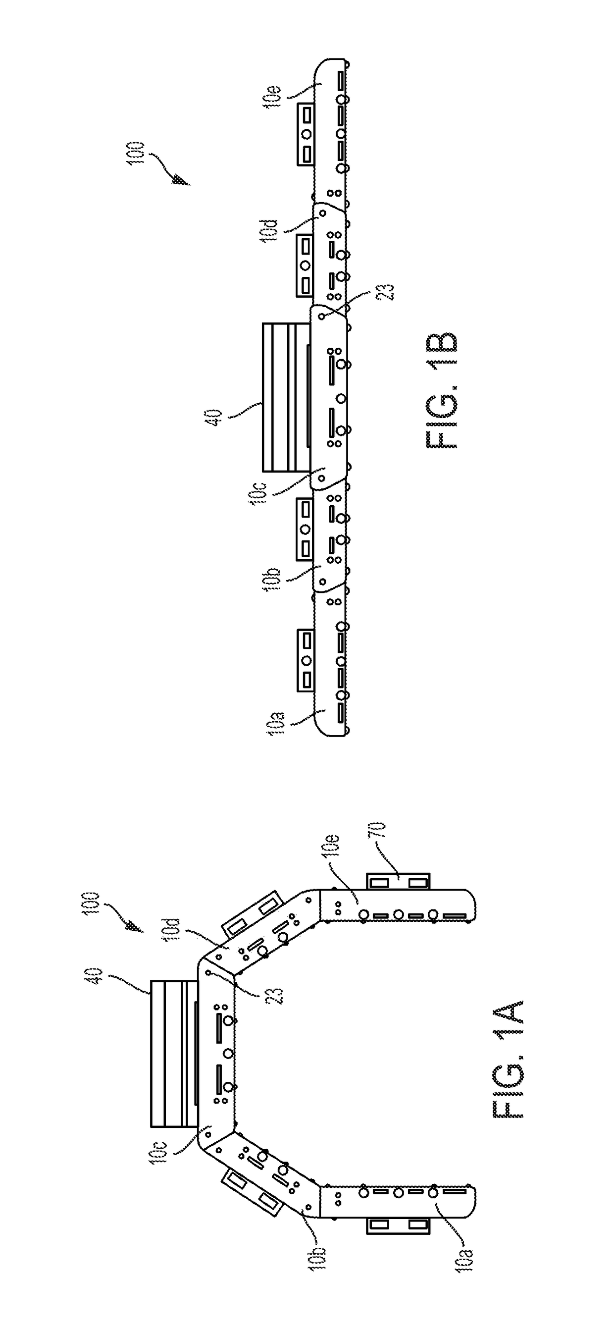
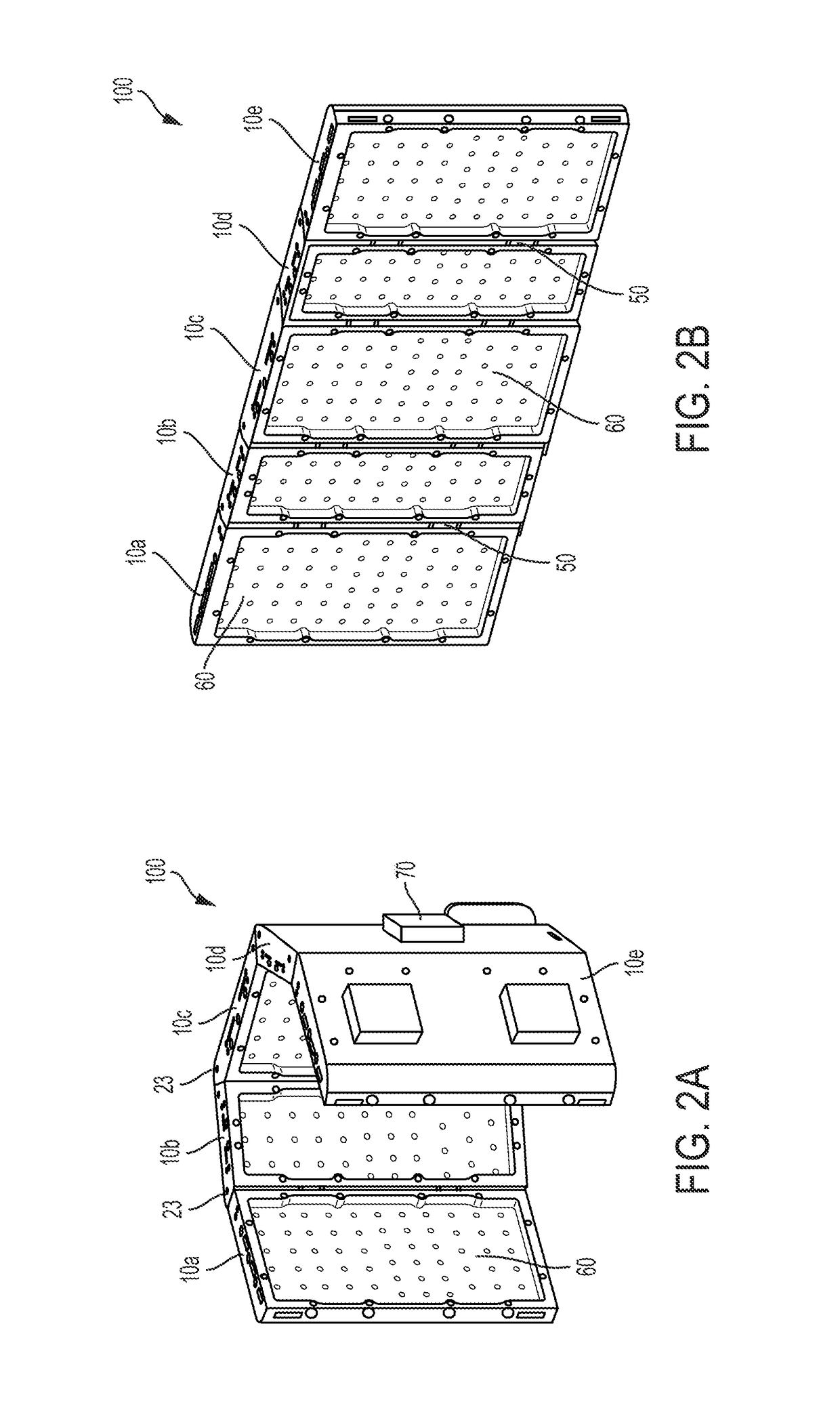
[0008]Generally, these conventional illuminators are used for phototherapy of acne, which typically does not require the administration of a photoactivatable agent for effective treatment. Thus, exposure to the light alone is generally sufficient treatment. Moreover, because multiple treatment sessions can be utilized to effectively treat the condition, uniformity of light across the target area during a given treatment is less of a concern in some situations. However, some forms of treatment involving PDT, such as the use of ALA to treat actinic keratosis, require specific and highly uniform intensity and color of light to achieve effectiveness. In these instances, successful PDT relies on the targeted delivery of both the correct quantity of the photoactivatable agent and the correct quantity (i.e., power and wavelength) of light to produce the desired photochemical reactions in the target cells. Thus, to achieve this, the light source must provide illumination to the target area and this illumination must be uniform with respect to both wavelength and power. The optical dead space that can occur at or near the hinges of conventional adjustable illuminators reduces the uniformity of the light along the treatment area, thereby reducing the effectiveness of PDT for these specific treatments. Moreover, these illuminators are also configured to adjust within a limited range, such that only a limited amount of surfaces on a patient's body may be treated, such as a patient's face and scalp. In addition, due to the various contours of a patient's body, the uniformity of light delivered by these conventional illuminators may vary substantially depending on the treatment area of the patient.
[0009]Therefore, it is an object of some embodiments of the present invention to reduce or eliminate these dead spaces and provide for a more uniform light distribution in an adjustable illuminator designed for

Problems solved by technology

However, due to the edges of the panels and the presence of the hinges, the light source(s) of one panel does not immediately adjoin the light source(s) of an adjacent panel.
The lack of light emitting from such areas, together with the uniform supply of power to the panels, can cause optical “dead space” in certain portions of the target treatment area.
The optical dead space that can occur

Method used


Image

  • Adjustable illuminators and methods for photodynamic therapy and diagnosis
  • Adjustable illuminators and methods for photodynamic therapy and diagnosis
  • Adjustable illuminators and methods for photodynamic therapy and diagnosis

Examples


Example

[0034]Various embodiments are described hereinafter. It should be noted that the specific embodiments are not intended as an exhaustive description or as a limitation to the broader aspects discussed herein. One aspect described in conjunction with a particular embodiment is not limited to that embodiment and can be practiced with any other embodiment(s).

[0035]As will be understood by one of skill in the art, for any and all purposes, particularly in terms of providing a written description, all ranges disclosed herein also encompass any and all possible subranges and combinations of subranges thereof. Any listed range can be easily recognized as sufficiently describing and enabling the same range being broken down into at least equal halves, thirds, quarters, fifths, tenths, etc. As a non-limiting example, each range discussed herein can be readily broken down into a lower third, middle third and upper third, etc. As will also be understood by one skilled in the art all language su...


PUM


Abstract

An illuminator for photodynamically diagnosing or treating a surface includes a plurality of panels. The illuminator further includes a plurality of light sources, each mounted to one of the plurality of panels. The plurality of light sources are configured to irradiate the surface with substantially uniform intensity visible light. The illuminator also includes a heat source configured to emit heat to a patient. The heat increases the generation of a photoactivatable agent and thus shortens the time needed to complete photodynamic therapy

Description

CROSS-REFERENCE TO RELATED APPLICATION[0001]This application claims the benefit of priority to U.S. Provisional Application No. 62 / 241,902 filed on Oct. 15, 2015 and is a continuation-in-part of U.S. patent application Ser. No. 15 / 292,731, filed on Oct. 13, 2016, which are hereby incorporated by reference in their entirety.FIELD[0002]The present disclosure relates generally to adjustable illuminators which provide a uniform distribution of visible light in a number of configurations and are suitable for use in photodynamic therapy and diagnosis, and to methods including operation of adjustable illuminators.BACKGROUND[0003]Photodynamic therapy (PDT), photodynamic diagnosis (PD), or photochemotherapy is generally used to treat and / or diagnose several types of ailments in or near the skin or other tissues, such as those in a body cavity. For example, PDT or PD may be used for treatment or diagnosis of actinic keratosis of the scalp or facial areas of a patient. In addition, PDT and PD ...

Claims


Application Information

Patent Timeline
IPC IPC(8): A61N5/06A61B5/00
CPCA61N5/062A61B5/0082A61N5/0616A61N2005/0626A61N2005/0652A61N2005/0633A61N2005/0642A61N2005/0663A61B5/0064A61N2005/0651A61N2005/0662A61B5/01A61B2560/0242
Inventor BOYAJIAN, THOMASCAROTA, MARKMAZEJKA, BRIAN
Owner DUSA PHARMA INC
Why Eureka
Try Eureka