Robot for surgical applications

a technology for surgical applications and robots, applied in the field of microrobotics, can solve the problems of limited use of micro-robots, lack of tactile feedback, limited dexterity and perception,

Inactive Publication Date: 2006-10-24
BOARD OF RGT UNIV OF NEBRASKA
View PDF55 Cites 1268 Cited by
  • Summary
  • Abstract
  • Description
  • Claims
  • Application Information

AI Technical Summary

Problems solved by technology

Micro-robots that mimic insects have been developed, though currently such micro-robots are of limited use due to their size and low-level agility (see Fearing, R. S. et al.
However, micro-robots have not been applied in laparoscopic or other minimally invasive surgery to date.
While minimally invasive surgical procedures reduce patient trauma, pain, recovery time, and hospital costs, there are several drawbacks to the technique.
For example, there are regions of the patient that are inaccessible with current methods, and there is a lack of tactile feedback and limited dexterity and perception.
A shape memory alloy (SMA) actuator has been proposed as well, but has some disadvantages, such as cooling, leaking electric current, and response delay (Fukuda et al.

Method used


Image

  • Robot for surgical applications
  • Robot for surgical applications
  • Robot for surgical applications

Examples


example 1

Mobile Mini-Robot

[0050]The constraints placed on the size of the micro-robot according to the present invention were factors in determining the size and shape of the initial prototype of the embodiment described herein. Also simplicity of design, stability of the platform were considered. The mobile robot was constructed to be cylindrical in shape, with the wheels of the mobile robot covering most of the body. The robot's diameter was designed to be less than 15 mm so as to be able to, in this embodiment, fit through a port in a tool that is currently used in laparoscopic surgical techniques.

[0051]The size and function of this robot dictated also the use of very small electric motors. The first motors tested were motors that are used to vibrate pagers and mobile phones; however, these motors were found to be inadequate to supply the torque needed to move the robot. A suitable motor was selected. The electronics selected initially consisted of a modified control chip for the brushles...

example 2

Biopsy Micro-Robot Design

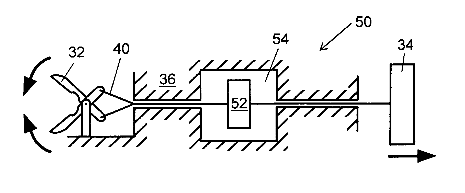
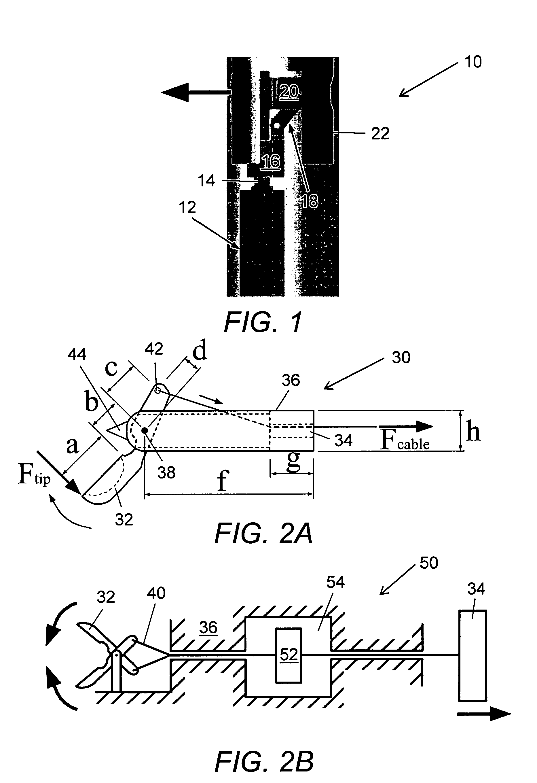
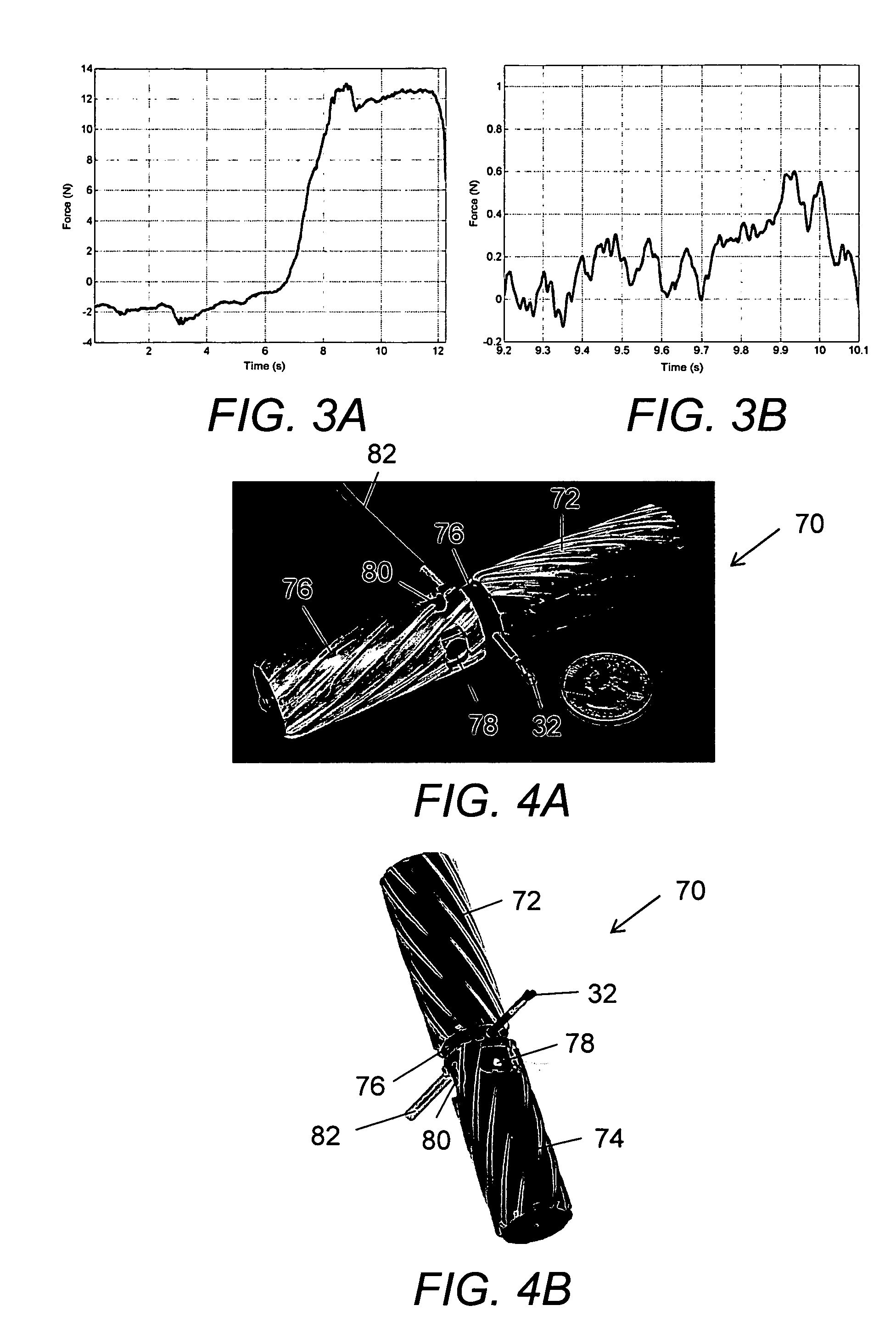
[0082]To establish the required clamping and drawbar forces necessary for successful biopsy, experimental biopsies were conducted. A biopsy forceps device that is commonly used for tissue sampling during esophago-gastroduodenoscopy (EGD) and colonoscopies was modified to measure cutting forces during tissue biopsy. These forceps 30, shown schematically in FIG. 2A, were composed of a grasper 32 on the distal end with a handle / lever system 34 on the proximal end. A flexible tube 36 was affixed to one side of the handle 34 and the other end was attached to the fulcrum point 38 of the biopsy grasper 32. A wire 40 enclosed in plastic (Teflon®) inside tube 36 was used to actuate the grasper 32. This wire 40 was affixed to the free end of the handle lever 34 and at the other end to the end of the grasper lever arm 42. Actuation of the handle lever 34 caused wire 40 to translate relative to the tube 36 and actuate the biopsy graspers 32. The tip of the forceps was e...


PUM


Abstract

The present invention provides a micro-robot for use inside the body during minimally-invasive surgery. The micro-robot includes an imaging devices, a manipulator, and in some embodiments a sensor.

Description

INTRODUCTION[0001]This application is a continuation-in-part of U.S. patent application Ser. No. 10 / 616,096 filed Jul. 8, 2003, now U.S. Pat. No. 7,042.184 incorporated herein by reference in its entirety.BACKGROUND OF THE INVENTION[0002]Interest in micro-robotics has increased rapidly in recent years. This is due mainly to technology development in the fields of microelectronics, micromachining, and microactuation. Currently, it is possible to build and test miniature systems that include numerous features, including sensors, actuators, and embedded control subsystems. The trend toward miniaturization is seen not only in industrial applications, but in medical applications as well.[0003]There are many industrial applications for micro-robots. Micro-robots are suitable for work in small and inaccessible places; for example, in dismantling and reassembling factory pipelines, inspection of small environments, measuring various parameters, miniature manipulation, repairs, micromachinin...

Claims


Application Information

Patent Timeline
Patent Type & Authority Patents(United States)
IPC IPC(8): B25J5/00A61B19/00B25J7/00
CPCA61B1/041A61B5/05A61B5/416A61B19/22B08B9/045B25J5/00B25J7/00B25J9/065A61B10/04A61B10/06A61B19/2203A61B2019/2242A61B2019/2249A61B34/70A61B34/71A61B34/30A61B34/72B33Y80/00
Inventor FARRITOR, SHANEOLEYNIKOV, DMITRYPLATT, STEPHEN R.RENTSCHLER, MARKDUMPERT, JASON
Owner BOARD OF RGT UNIV OF NEBRASKA
Why Eureka
Try Eureka