Apparatus and method for minimally invasive surgery using rotational cutting tool

a cutting tool and surgical technique technology, applied in the field of minimally invasive surgical tools and techniques, can solve the problems of increasing the risk of complications, not allowing the use of additional instruments, and causing great discomfort to patients, and achieve the effect of cutting body tissu

Inactive Publication Date: 2006-04-25
MAQUET CARDIOVASCULAR LLC
View PDF49 Cites 396 Cited by
  • Summary
  • Abstract
  • Description
  • Claims
  • Application Information

AI Technical Summary

Benefits of technology

[0013]An embodiment of the present invention includes a surgical instrument having a tube and a shaft within the tube. The tube and the shaft each have a distal end and a proximal end. The distal end of the tube includes a cutting edge, and the distal end of the shaft includes a blade. Either the blade or the shaft is rotatable with respect to the other such that the blade cooperates with the cutting edge to cut body tissue.

Problems solved by technology

Thus, pivoting scissors 190 generally do not allow additional instruments to be used through the same incision.
This technique can create great discomfort to the patient and increase the risk of complications because of the length of the incision and the open surgery.
Also, after such a surgery, the time required for the patient to heal is relatively long.
This technique, even though it is less invasive than an open incision, is cumbersome for the surgeon to accomplish because the surgeon must manipulate two separate instruments from two different directions or positions.
Also, the two-incision technique is difficult because the surgeon must observe the instruments and tissue in the body cavity from two different directions.
Each of these ligation techniques requires a separate step, which increases the time required for the surgery.

Method used


Image

  • Apparatus and method for minimally invasive surgery using rotational cutting tool
  • Apparatus and method for minimally invasive surgery using rotational cutting tool
  • Apparatus and method for minimally invasive surgery using rotational cutting tool

Examples


Embodiment Construction

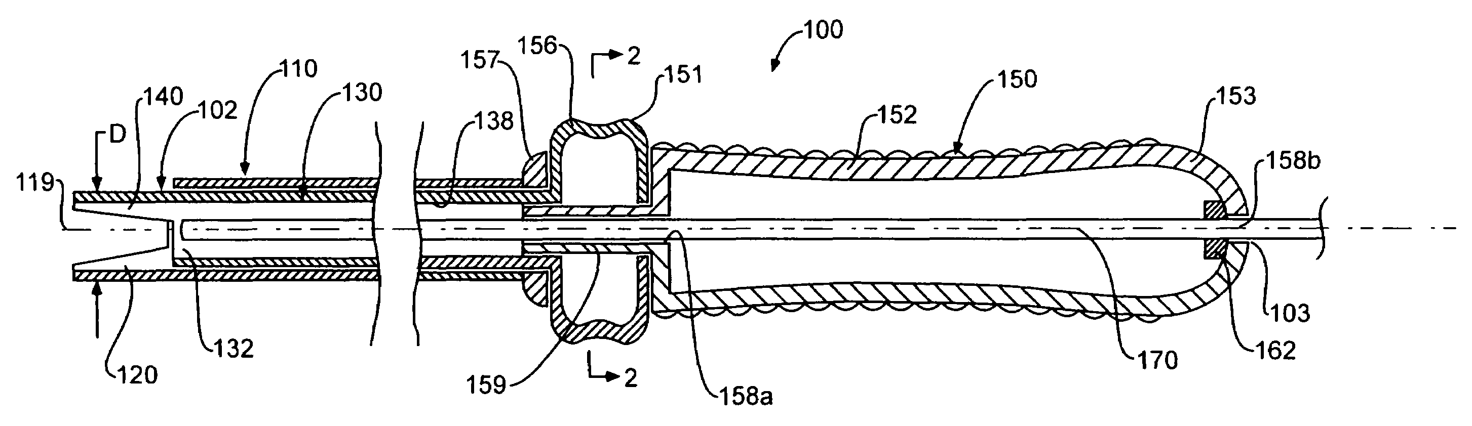
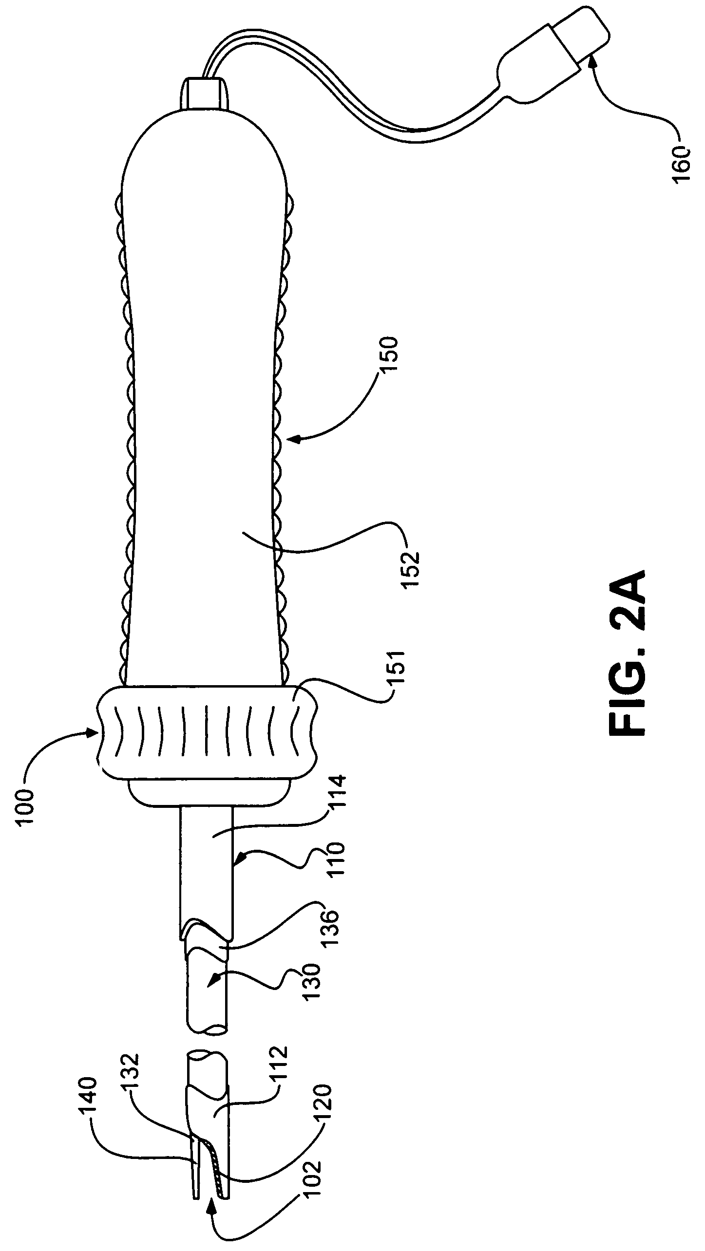
[0043]FIG. 2A shows an embodiment of a surgical instrument 100 of the invention. Surgical instrument 100 includes a tube 110 and a shaft 130. Tube 110 has a distal end 112 and a proximal end 114. Similarly, shaft 130 includes a distal end 132 and a proximal end (not shown). Distal end 112 of tube 110 includes an outer blade 120 extending longitudinally therefrom. Distal end 132 of shaft 130 includes an inner blade 140 extending longitudinally therefrom. Shaft 130 is rotatably disposed within tube 110 such that inner blade 140 is revolvable about the longitudinal axis of tube 110. As shaft 130 rotates, causing inner blade 140 to revolve about the longitudinal axis, inner blade 140 cooperates with outer blade 120 to create a rotational cutting action between the blades.

[0044]Surgical instrument 100 preferably includes a handle 150. As shown in FIG. 2A, handle 150 includes an elongated grip 152. Handle 150 can be configured to provide an ergonomic holding and controlling location for t...


PUM


Abstract

An apparatus and method for minimally invasive surgery using a cutting tool with rotational cutting edges. The surgical instrument includes a tube having a distal end and a cutting edge at the distal end. A handle is attached to the proximal end of the tube. Within the tube is a shaft having a longitudinally extending blade at its distal end that is adjacent to the distal end of the tube. The blade is revolvable about the longitudinal axis of the instrument to provide rotational cutting action. One or both of the blade and the cutting edge on the tube can be electrically energized to provide for electrocauterization of the body tissue being cut.

Description

CROSS REFERENCE TO RELATED APPLICATIONS[0001]This application is a continuation of application Ser. No. 10 / 022,680 Dec. 17, 2001, now U.S. Pat. No. 6,702,813 which is a continuation of Ser. No. 09 / 522,254 Mar. 9, 2000 now U.S. Pat. No. 6,428,539.FIELD OF THE INVENTION[0002]The invention relates generally to minimally invasive surgical tools and techniques and, particularly, to a method and apparatus for cutting body tissue using a bipolar or monopolar electrocautery tool with rotational cutting blades.BACKGROUND OF THE INVENTION[0003]Minimally invasive surgery such as laparoscopic, endoscopic, hysteroscopic, and arthroscopic surgery is becoming more widely used because it is less traumatic to the patient, generally involves less hospitalization time, less discomfort and less risk to the patient, and can be less costly than traditional open surgery. A minimally invasive surgical procedure is typically performed by making a small incision in the patient which provides access to the ar...

Claims


Application Information

Patent Timeline
Patent Type & Authority Patents(United States)
IPC IPC(8): A61B18/12A61B17/00A61B17/22A61B17/32A61B18/00A61B18/14
CPCA61B17/320016A61B17/32002A61B18/1482A61B17/320783A61B17/00008A61B17/32A61B2018/1861A61B2017/320741A61B2018/00601A61B2018/126A61B2018/00202
Inventor BAXTER, JEFFREY W.DAVIS, JOHN
Owner MAQUET CARDIOVASCULAR LLC
Why Eureka
Try Eureka