SLM projection display with series DMD illuminator

Inactive Publication Date: 2003-01-23
TEXAS INSTR INC
View PDF7 Cites 51 Cited by
  • Summary
  • Abstract
  • Description
  • Claims
  • Application Information

AI Technical Summary

Benefits of technology

0012] The present invention adds DMD illumination modulators in series with projection SLM(s) to produce high-performance projection displays with improved optical efficiency, reliability, and lower maintenance requirements.
0013] This approach eliminates the vibration, audible noise, and safety problems associated with high speed rotating color filter wheels commonly used in SLM projectors. In addition, the DMD illumination modulators provide a means for controlling the light to each portion of the projection SLM(s), providing variable levels of each color to individual pixels of the projection SLM. For example, color illumination can b

Problems solved by technology

DMD based projection displays typically use rotating color wheels, which are optically inefficient, for color-plane separation.
These color wheels require motors, balanced parts, and rotary sensors all of which contribute negatively to system reliability, size, safety, noise, maintenance, and cost.
By design, the filter panels only let specific wavelengths of light through during

Method used


Image

  • SLM projection display with series DMD illuminator
  • SLM projection display with series DMD illuminator
  • SLM projection display with series DMD illuminator

Examples


Example

[0038] FIGS. 7a and 7b are top and front views of a schematic drawing for a first embodiment of the present invention, which uses a single illumination DMD in series with the two parallel projection SLMs to implement an improved version of the system of FIG. 2a without a rotating color wheel and using the yellow-magenta dichroic scheme discussed in FIG. 6. White light from a lamp 701 is collected by a reflector 700 and directed on to the surface of an illumination DMD 702 in a direction perpendicular to the surface of the DMD. The micro-mirrors are sequentially switched between +x degrees and -x degrees with light reflecting from the mirrors when tilted in the +x direction 703 being reflected off a first turning mirror 704, through a red dichroic 705, on to the surface of a yellow dichroic 706. Light reflecting from the mirror when tilted in the -x direction 707 is reflected off a second turning mirror 708, through the red dichroic 705, on to the surface of a magenta dichroic 709. T...

Example

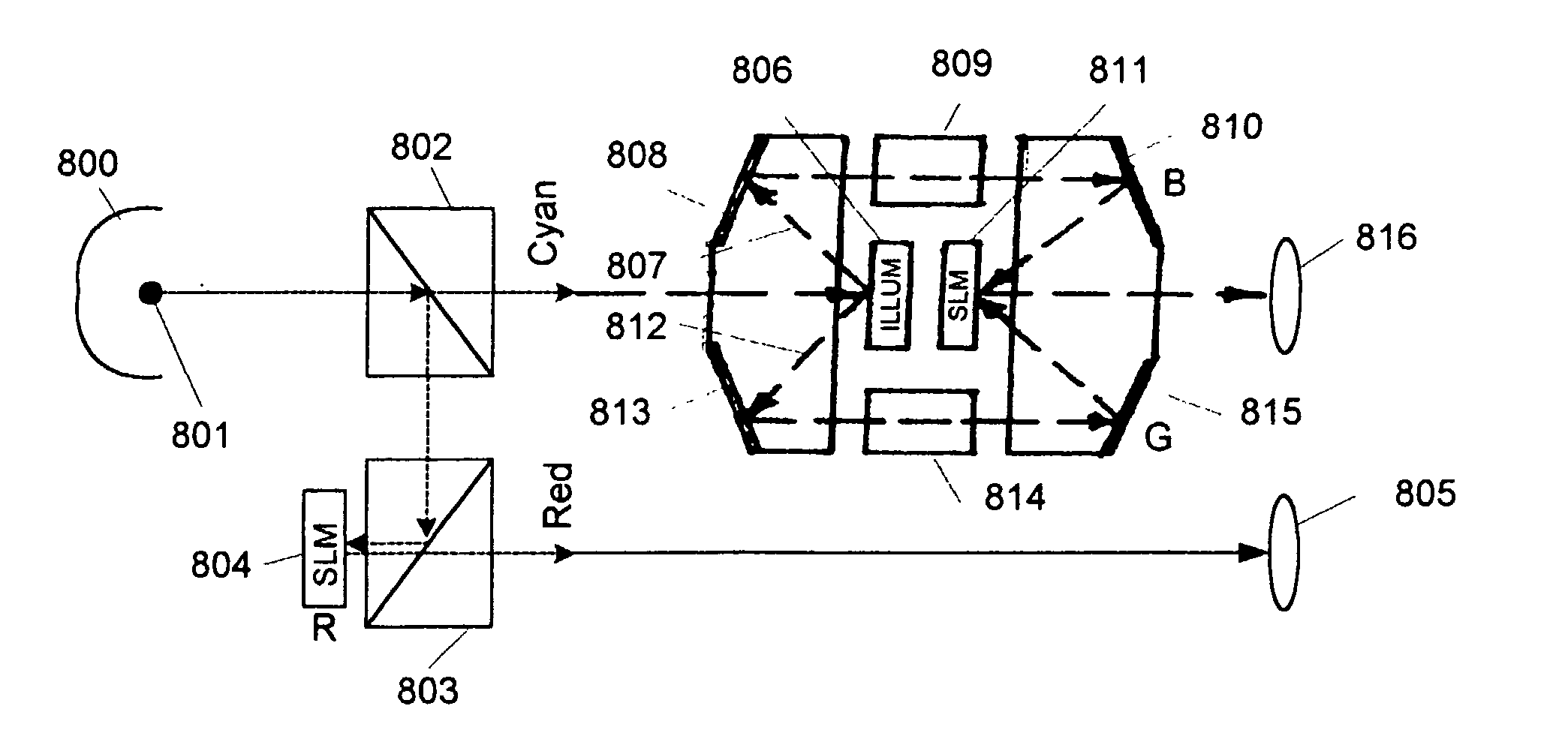
[0042] FIG. 8 is a schematic drawing for a second embodiment of the present invention, which also uses a single illumination DMD in series with green-blue projection SLM, but splits off the red light and send it directly to a dedicated red SLM to implement an improve version of the system of FIG. 2b without a rotating color wheel. White light from a lamp 801 is collected by reflector 800 and directed into a first TIR prism 802 where the red light is reflected off an internal surface into a second TIR prism 803. Here, the red light is again reflected off an internal surface on to the reflective surface of the red SLM 804, where it is modulated based on the red image data content and reflected from the ON pixels of the SLM back through the second TIR prism 803 into a projection lens 805. In parallel, cyan light passes through the first TIR prism 802 on to the micro-mirrors of an illumination DMD 806 along a path that is perpendicular to the surface of the DMD. The micro-mirrors of the...

Example

[0043] FIG. 9 is a schematic drawing for a third embodiment of the present invention, which uses two illumination DMDs in series with two projection SLMs to implement an improve performance projection display system without a rotating color wheel. In this configuration, white light from a light source (not shown) is passed through a first turning mirror 900 onto the surface of a yellow dichroic 901 from which yellow (red-green) light is reflected into a first yellow illumination DMD 902 and magenta (red-blue) light is passed through on to the surface of a second magenta illumination DMD 903. The yellow and magenta light is respectively modulated to optimally control the system performance by means of these two illumination DMDS. Modulated light from the yellow illumination DMD 902 is reflected off the ON micro-mirrors back on to the yellow dichroic 901. This light is then reflected off the yellow dichroic 901, off the reflective surface of the first turning mirror 900, off the refle...


PUM


Abstract

The addition of DMD illumination modulator(s) 702 in series with projection SLM(s) 706/709 to produce high-performance projection displays with improved optical efficiency, reliability, and lower maintenance requirements. This approach eliminates the vibration, audible noise, and safety problems associated with high speed rotating color filter wheels 203 commonly used in SLM projectors and controls the light applied to individual areas of the projection SLM(s).

Description

FIELD OF THE INVENTION[0001] The present invention relates to spatial light modulator (SLM) projection displays and particularly to the illumination source in such displays.BACKGROUND OF THE INVENTION[0002] In current SLM projection displays, such as DMD.TM. or LCD, the projector's lamp emits broadband (white) light, which is split into primary or secondary color components by dichroic surfaces in stationary prisms, mirrors, or rotating panels, such as color wheels or drums. These filtered planes of light are coupled to the projection SLM(s) in synchronization with pixelated image data. In the case of a DMD projector, the projection DMD's mirrors are controlled by the image data to be either in the correct state for color projection to the screen or out of the field of view. Integrators are often added to homogenize the illumination.[0003] DMD based projection displays typically use rotating color wheels, which are optically inefficient, for color-plane separation. These color wheel...

Claims


Application Information

Patent Timeline
IPC IPC(8): G02B26/08H04N5/74H04N9/31
CPCG02B26/0841G03B21/20H04N5/7441H04N5/7458G03B33/06H04N9/3126H04N9/3155G03B21/2066H04N9/3105G03B33/12G03B21/005G03B21/26H04N9/3102H04N9/3111G03B33/14G03B33/08
Inventor PENN, STEVEN M.
Owner TEXAS INSTR INC
Why Eureka
Try Eureka