
Lighting fixture with enclosed wiring

a technology of electrical wiring and light fixtures, applied in lighting and heating apparatus, lighting support devices, lighting source combinations, etc., can solve problems such as inacceptable external threading of wiring

Inactive Publication Date: 2003-06-26
MINKA LIGHTING
View PDF0 Cites 6 Cited by
  • Summary
  • Abstract
  • Description
  • Claims
  • Application Information

AI Technical Summary

Problems solved by technology

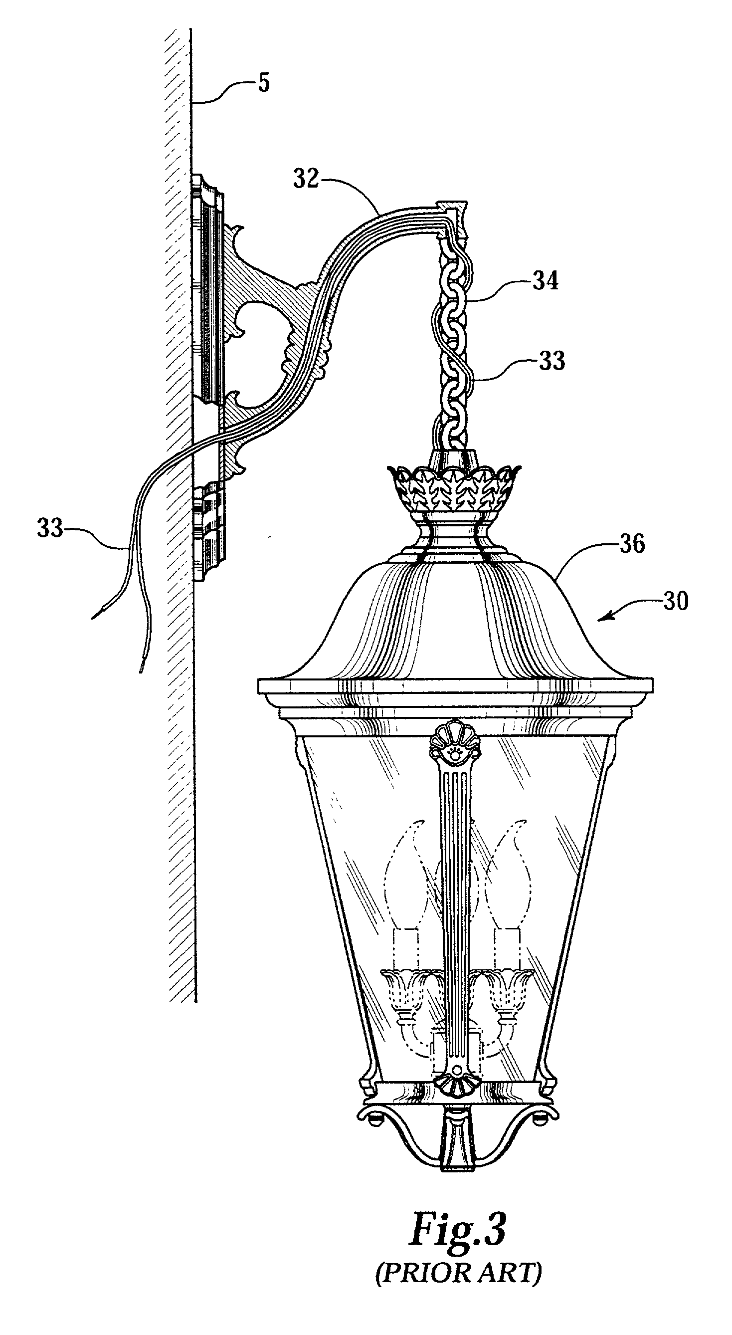
Threading the wire around the chain or rod is normally acceptable in indoor applications, however, the Underwriters Laboratories (UL) specifies that for outdoor use where the wiring may be exposed to water that externally threading the wiring is not acceptable.

Method used


Image

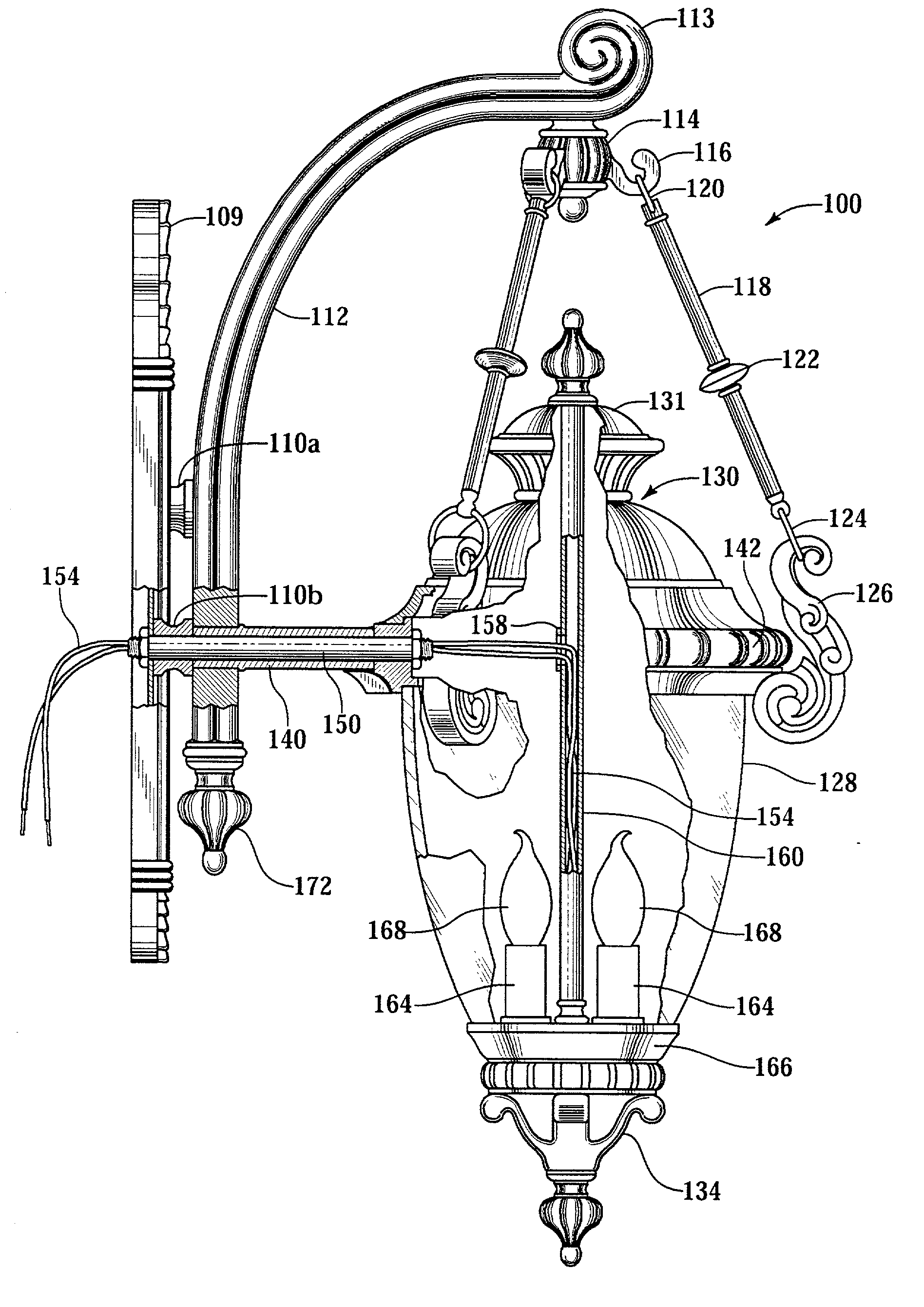
  • Lighting fixture with enclosed wiring
  • Lighting fixture with enclosed wiring
  • Lighting fixture with enclosed wiring

Examples


Embodiment Construction

[0017] The present invention will now be described more fully hereinafter with reference to the accompanying drawings in which a preferred embodiment of the invention is shown. This invention may, however, be embodied in many different forms and should not be construed as being limited to the embodiment set forth herein. Rather, the embodiment is provided so that this disclosure will be definite and enabling, and will fully convey the scope of the invention to those skilled in the art.

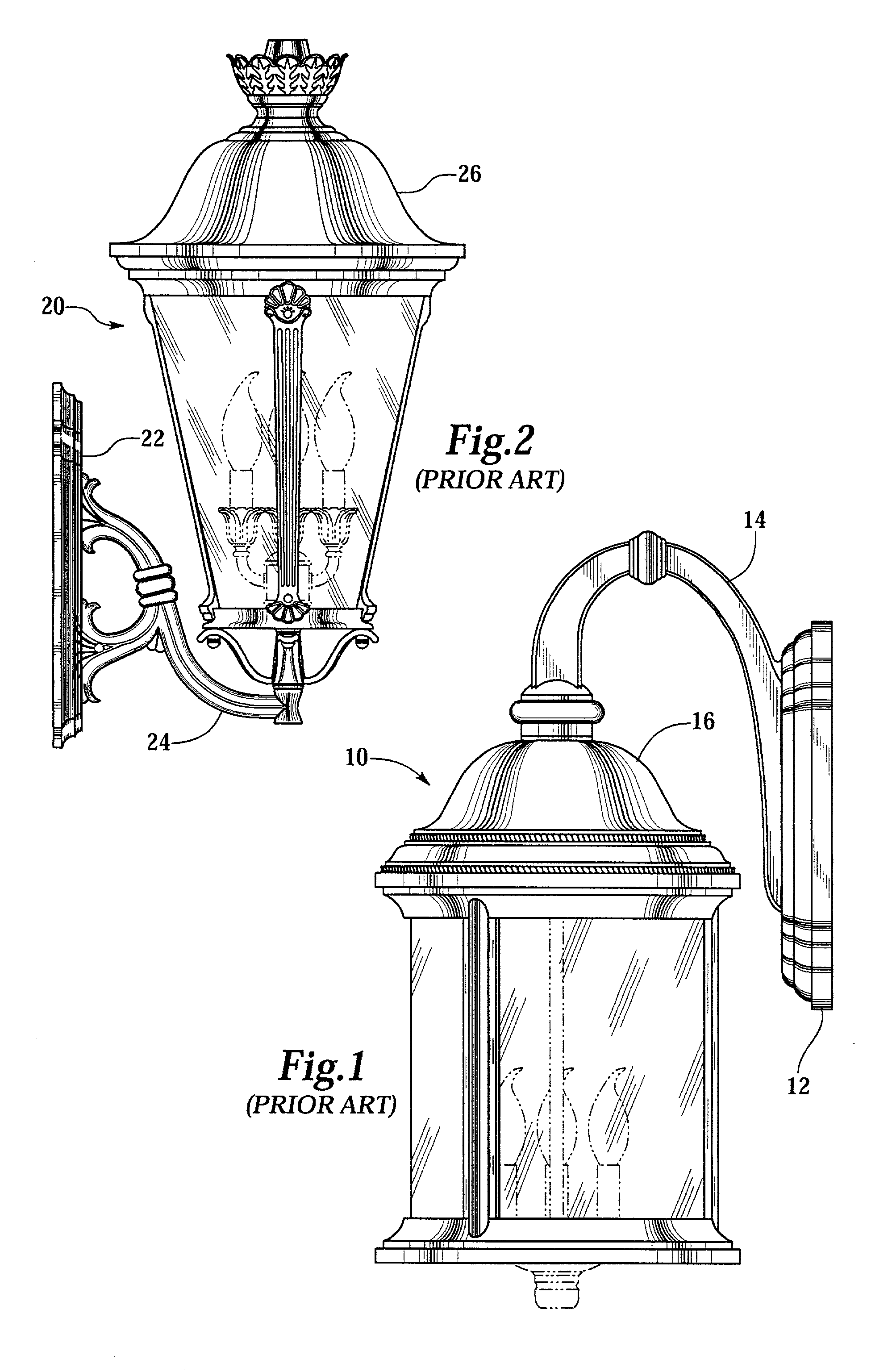
[0018] FIGS. 1, 2, and 3 are prior art fixtures as previously discussed and described in the Background section of this application.

[0019] FIGS. 4, 5, and 6 illustrate a side view, a top view and a bottom view of an exemplary embodiment of the lighting fixture 100 of the present invention. A lamp housing 130 is connected to a curved upper support arm 112 securely fixed to a backplate 109 using one or more connecting mechanisms 110a and 110b. The connecting mechanisms 110a and 110b may be part of the up...


PUM


Abstract

A lighting fixture (100) for outdoor use having electric wiring (154) enclosed in a rear support arm (140). The lighting fixture includes an upper support arm (112) and a plurality of downwardly disposed supporting rods (118) connected to the lamp housing (116) and the upper support arm.

Description

[0001] The present application claims priority on U.S. patent application Ser. Nos. 29 / 148,515, filed Sep. 20, 2001; 29 / 148,527, filed Sep. 20, 2001; 29 / 148,516, filed Sep. 20, 2001; 29 / 148,517, filed Sep. 20, 2001; and 29 / 151,010, filed Nov. 30, 2001.BACKGROUND OF PRESENT INVENTION[0002] 1. Field of the Invention[0003] The present invention relates to electric lighting fixtures. More particularly it relates to light fixtures with enclosed electric wiring therein.[0004] 2. Background of the Invention[0005] Long before the invention of the light bulb, lighting fixtures have been commonly used both indoor and outdoor. They have been used first with gas lighting systems and were later designed for use with electric light bulbs. The main purpose of lighting fixtures is to enclose the light bulbs therein and provide protection to the light bulb from external sources. Another common use of the lighting fixtures in some applications is to divert the direct beam of light so as to provide ad...

Claims


Application Information

Patent Timeline
Patent Type & Authority Applications(United States)
IPC IPC(8): F21S8/00F21V21/116F21V27/00
CPCF21S8/033F21V21/116F21Y2113/00F21W2131/10F21W2121/00F21V27/00
Inventor DE' ARMOND, ROBERT
Owner MINKA LIGHTING
Learn More