Light emitting panel and light emitting apparatus having the same

a technology of light emitting apparatus and light emitting panel, which is applied in the direction of static indicating device, identification means, instruments, etc., can solve the problems of complex passive matrix driving, high power consumption of passive matrix organic light emitting device, and insatiable cathode ray tube and liquid crystal display devi

Inactive Publication Date: 2004-01-08
SAMSUNG DISPLAY CO LTD
View PDF4 Cites 42 Cited by
  • Summary
  • Abstract
  • Description
  • Claims
  • Application Information

AI Technical Summary

Problems solved by technology

Thus, both of the cathode ray tube and the liquid crystal display devices are not satisfactory.
However, the passive matrix organic light-emitting device consumes much power....

Method used


Image

  • Light emitting panel and light emitting apparatus having the same
  • Light emitting panel and light emitting apparatus having the same
  • Light emitting panel and light emitting apparatus having the same

Examples


Embodiment Construction

[0045] Hereinafter the preferred embodiment of the present invention will be described in detail with reference to the accompanying diagrams.

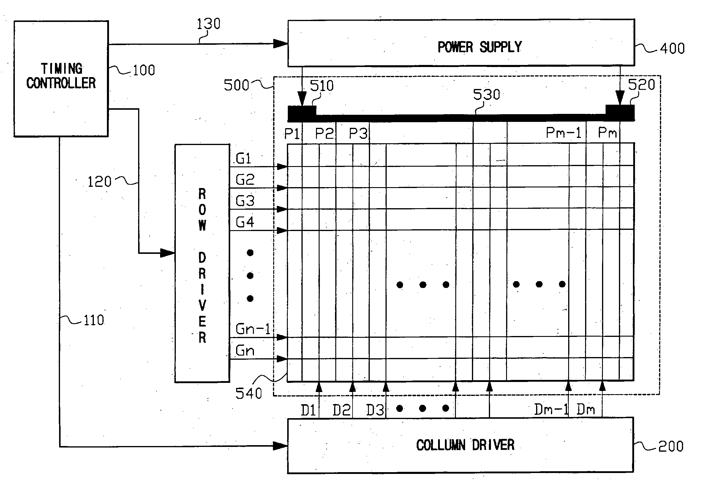
[0046] FIG. 3 is a block diagram showing an organic light-emitting apparatus according to a first exemplary embodiment of the present invention.

[0047] Referring to FIG. 3, an organic light-emitting apparatus according to a first exemplary embodiment of the present invention includes a timing controller (or a timing control part) 100, a column driver (or a column driving part) 200, a row driver (or a row driving part) 300, a power supply (or a power supplying part) 400 and an organic light-emitting panel 500.

[0048] The timing controller 100 receives an external image signal and a control signal of the image signal from an external device such as a graphic controller (not shown) to generate first and second timing signals of 110 and 120. The first timing signal 110 is transferred to the column driver 200. The second timing signal 120 is transferr...


PUM


Abstract

An organic light-emitting panel includes a data line, a scan line, a voltage applying line, a switching device, an organic light emitting device and a driving device. The voltage applying line satisfies a condition expressed as <math-cwu id="MATH-US-00001"> <NUMBER>1</NUMBER> ¡ a ^ V ( max ) n < A ¡ a ^ Vdata GS n [ Volt ] , <mathematica-file id="MATHEMATICA-00001" file="US20040004444A1-20040108-M00001.NB"/> <image id="EMI-M00001" wi="216.027" he="25.9119" file="US20040004444A1-20040108-M00001.TIF" imf="TIFF" ti="MF"/> </MATH-CWU> wherein DeltaVmax is a maximum voltage drop, 'n' is a number of pixels those are electrically connected to the voltage applying line, 'A' is a correction coefficient that is in a range from about 1 to about 2, DeltaVdata is a voltage difference between the gray scales, and GS is a number of gray scale. According to the organic light-emitting panel, the voltage drop of the voltage applying line is reduced.

Description

[0001] This application relies for priority upon Korean Patent Application No.2002-38995 filed on Jul. 5, 2002, the contents of which are herein incorporated by reference in its entirety.[0002] 1. Field of the Invention[0003] The present invention relates to a light emitting panel and a light emitting apparatus having the light emitting panel, and more particularly to a light emitting panel having reduced cross talk and a light emitting apparatus having the light emitting panel.[0004] 2. Description of the Related Art[0005] Recently, a cathode ray tube (CRT) display device and a liquid crystal display device are widely used as display devices. The cathode ray tube has a heavy weight and a large size. The liquid crystal display device has a low luminance, a low light using efficiency and a narrow viewing angle. Thus, both of the cathode ray tube and the liquid crystal display devices are not satisfactory.[0006] One of next display devices is a light emitting apparatus. The light emit...

Claims


Application Information

Patent Timeline
IPC IPC(8): G09F9/30H01L51/50G09G3/20G09G3/30G09G3/32H01L27/32
CPCG09G3/3208G09G3/3233G09G2300/0426H01L27/3244G09G2320/0209G09G2320/0223G09G2330/02G09G2300/0842H10K59/12G09G3/30
Inventor CHOI, BEOHM-ROCKCHOI, JOON-HOOCHUNG, JIN-KOO
Owner SAMSUNG DISPLAY CO LTD
Why Eureka
Try Eureka