
Keratometric to apical radius conversion

a technology of apical radius and keratometrics, which is applied in the field of human corneal refractive surgery, can solve the problems of not having the resolution necessary to achieve optimal refractive, not being able to achieve the accuracy required for shape, and not being able to precisely spherical the cornea

Inactive Publication Date: 2002-08-22
LASERSIGHT TECH
View PDF0 Cites 15 Cited by
  • Summary
  • Abstract
  • Description
  • Claims
  • Application Information

AI Technical Summary

Problems solved by technology

These older generation systems cannot achieve the accuracy required to shape the ablation profiles described in this disclosure, nor do they have the resolution necessary to achieve optimal refractive results.
However, the cornea is not exactly spherical, and ablation systems and techniques which determined a closest fit sphere to a patient's cornea where somewhat inaccurate because of the differences between the actual shape of the cornea and the best fit sphere modeling the cornea used by the ablation system.
However, in practice, this is rarely the case, and toroidal surfaces too cause inaccuracies in ablation systems due to the differences between the best fit toroidal surface and the actual shape of the patient's cornea.
The result of this inability to achieve a confocal condition frequently results in glare, halos, and loss of night vision.

Method used


Image

  • Keratometric to apical radius conversion
  • Keratometric to apical radius conversion
  • Keratometric to apical radius conversion

Examples


Embodiment Construction

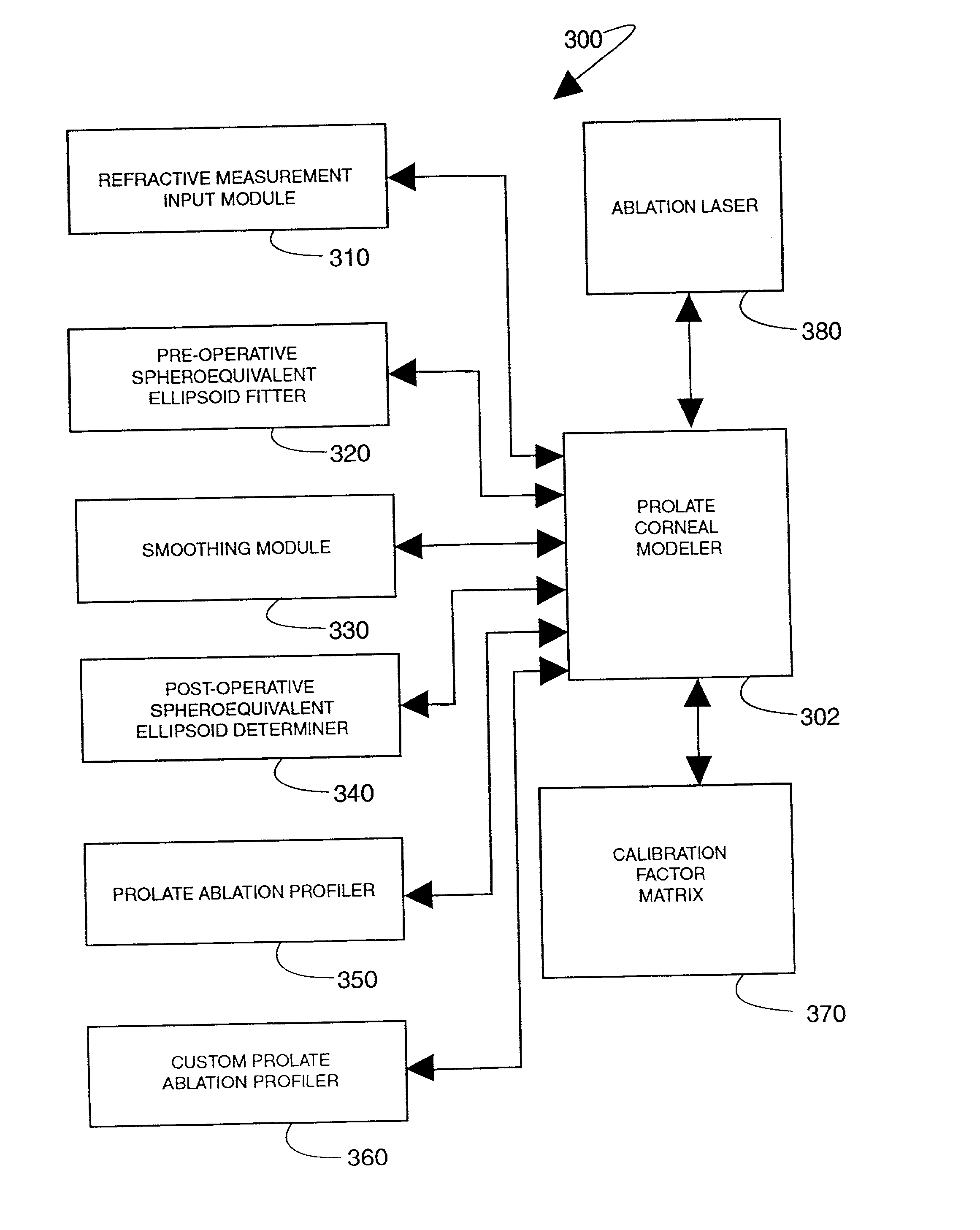
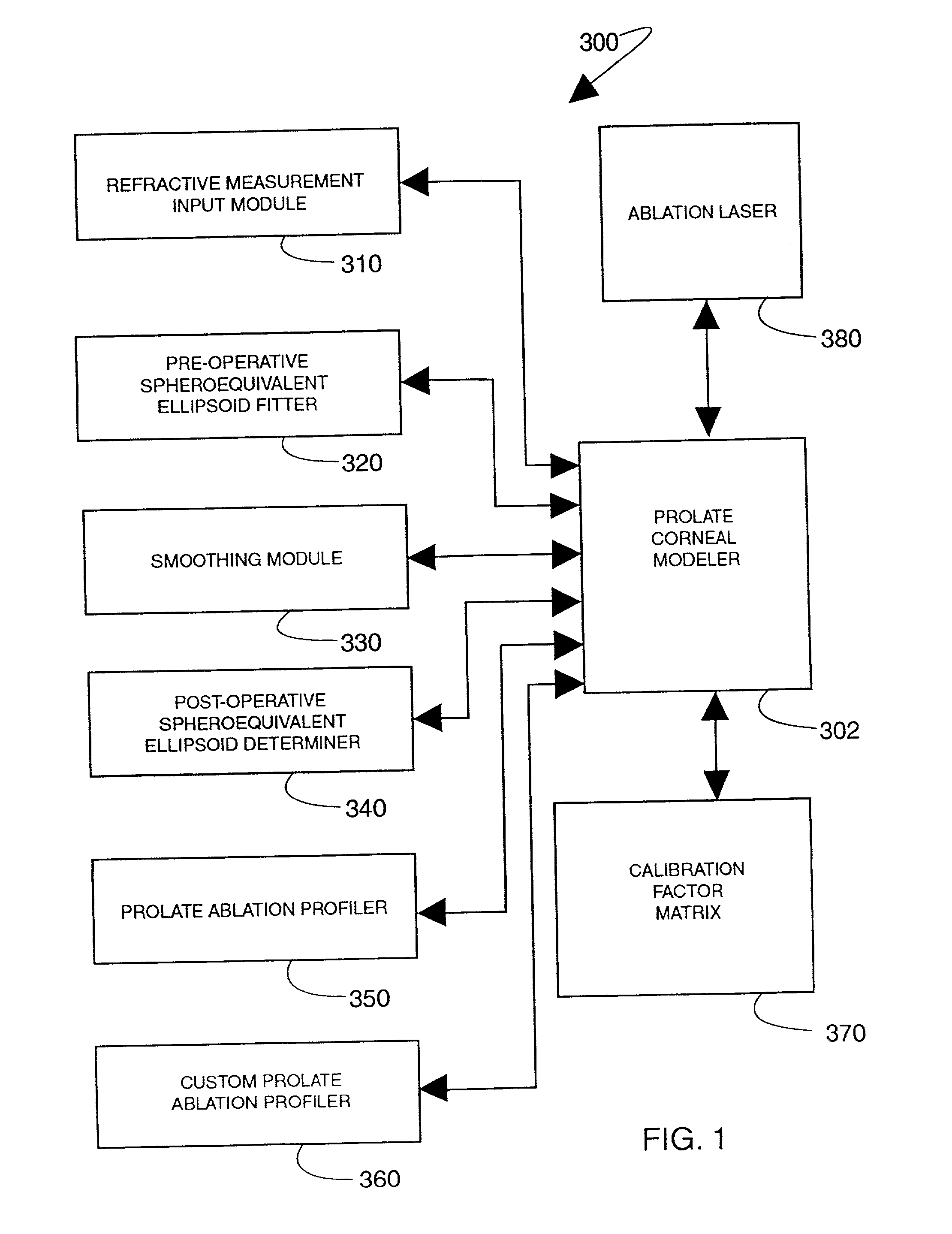
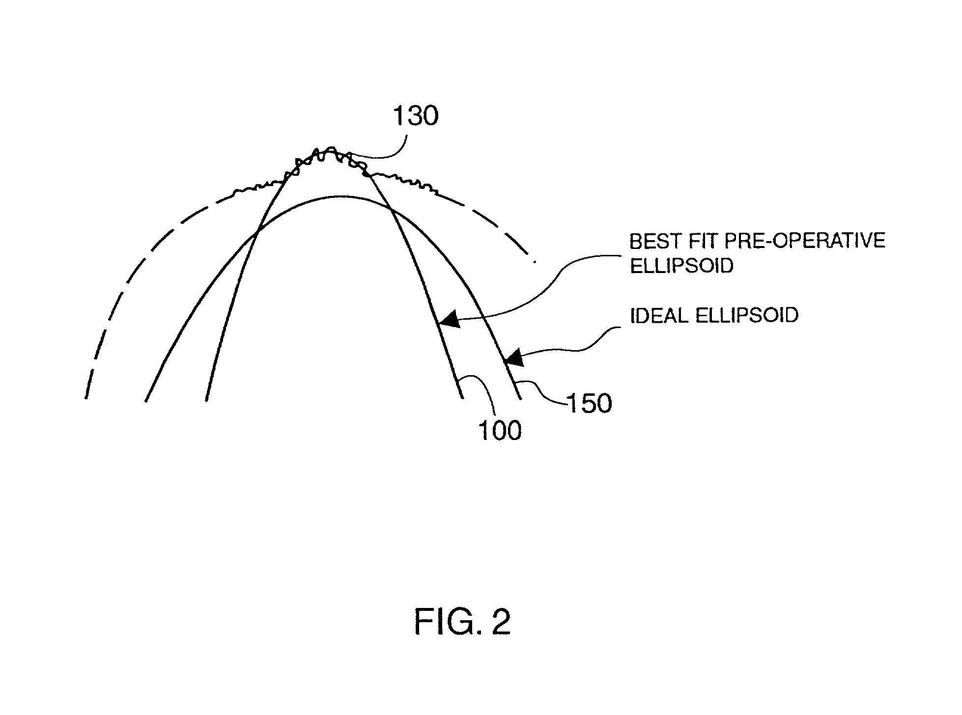
[0030] The present invention provides apparatus and techniques for performing prolate shaped corneal reshaping. In accordance with the techniques, a spheroequivalent ellipsoid model is implemented to provide a pre- and post-operative approximation of a cornea, and a desired prolate shaped ablation profile is determined based on a desired ellipsoidal shape. In accordance with the principles of the present invention, the ellipsoid model has only three degrees of freedom (not four as in a conventional biconic) to define a desired ablation profile, providing extremely accurate and predictable long term vision correction.

[0031] To arrive at an ellipsoid model having only three numbers of freedom, a spheroequivalent (SEQ) value of eccentricity .epsilon. or asphericity Q (1+Q.sub.SEQ)=(1-.epsilon..sub.SEQ.sup.2) where Q.sub.SEQ=-.epsilon..sub.SEQ.sup.2, is generated. The eccentricity .epsilon. value replaces two numbers of freedom (i.e., eccentricities) in an otherwise conventional biconic...


PUM


Abstract

The present invention provides apparatus and techniques for performing prolate shaped corneal reshaping using an ellipsoid corneal modeler. In accordance with the principles of the present invention, an ellipsoid corneal modeler is implemented with the well behaved conicoid, combined with a modeled surface which can be used for astigmatic treatments. An ellipsoid corneal modeler includes an ellipsoid fitter which utilizes two radii of curvature, asphericity (Q), and a surface rotation about the pupil center (roation of theta), yielding the equation: <math-cwu id="MATH-US-00001"> <number>1< / number> x 2 R x + y 2 R y + z z ( 2 ⁢ R x ⁢ R y ( 1 + Q ) ⁢ R x + R y ) = 2 ⁢ R x ⁢ R y ( 1 + Q ) ⁢ R x + R y ( 5 ) <mathematica-file id="MATHEMATICA-00001" file="US20020115988A1-20020822-M00001.NB" / > <image id="EMI-M00001" wi="216.027" he="30.9582" file="US20020115988A1-20020822-M00001.TIF" imf="TIFF" ti="MF" / > < / math-cwu> Moreover, a conversion is provided to convert between measurements obtained by a keratometer, and apical radii. In a further embodiment provided by the present invention, conversion is made possible between radii measurements obtained clinically (e.g., using a keratometer) and radii measurements at the apex, i.e., keratometric to apical radius conversion.

Description

[0001] This application claims priority from U.S. Provisional Application, Serial No. 60 / 262,378, entitled "Keratometric to Apical Radius Conversion", filed Jan. 19, 2001; and from U.S. patent application Ser. No. 09 / 679,077, entitled "Prolate Shaped Corneal Reshaping", filed Oct. 5, 2000, which itself claims priority from U.S. Provisional Appl. No. 60 / 223,728, entitled "Prolate Shaped Corneal Reshaping", filed Aug. 8, 1999, and U.S. Provisional Appl. No. 60 / 157,803, entitled "Prolate Shaped Corneal Reshaping", filed Oct. 5, 1999. All of these applications are expressly incorporated herein by reference.[0002] This application is a continuation-in-part of U.S. patent application Ser. No. 09 / 679,077.[0003] 1. Field of the Invention[0004] This invention relates generally to apparatus for use in reshaping the cornea of a human eye. More particularly, it relates to human corneal refractive surgery and techniques and apparatus used to model the human eye as an ellipsoid to determine a des...

Claims


Application Information

Patent Timeline
IPC IPC(8): A61B3/107A61B19/00A61F9/01G09B23/28
CPCA61B3/0025A61B3/107A61B19/50A61F9/00804A61F2009/00872A61F2009/00882G09B23/28A61B34/10
Inventor HOLLADAY, JACK T.
Owner LASERSIGHT TECH
Learn More