Hand-held autonomous visual acuity measurement apparatus and visual acuity measuring method

a technology of visual acuity measurement and hand-held, which is applied in the field of hand-held autonomous visual acuity measurement apparatus and visual acuity measurement method, can solve the problems of inability to independently complete the visual acuity measurement, inaccurate actual measurement, and large volume of traditional optometry instruments, so as to achieve miniaturization and portability of optometry systems, and convenient visual acuity measurement

Active Publication Date: 2020-06-30
SUZHOU SIHAITONG INSTR
View PDF15 Cites 0 Cited by
  • Summary
  • Abstract
  • Description
  • Claims
  • Application Information

AI Technical Summary

Benefits of technology

[0027]The above mentioned technical scheme employed by the present disclosure has the following advantages over the prior art: the present disclosure employs the motor to drive the first image collector to automatically focus, requires no assistance from a second person to adjust the focus, and the subject may complete the vision measurement by oneself, the present invention has capability of being operated by one subject, and convenient visual acuity measurement, and can effectively achieve miniaturization and portability of optometry systems.

Problems solved by technology

At present, the traditional optometry instruments have a large volume, and are not portable.
And, it requires the user have certain professional knowledge, or it needs the professional optometrist to measure the visual acuity of the subject, and the subject cannot independently complete the visual acuity measurement.
For those who do not cooperate with the measurement, or the measurer does not have enough professional skills, it results in inaccurate actual measurement results, which directly affect the accuracy of vision correction when configuring glasses.

Method used


Image

  • Hand-held autonomous visual acuity measurement apparatus and visual acuity measuring method
  • Hand-held autonomous visual acuity measurement apparatus and visual acuity measuring method

Examples


Embodiment Construction

[0034]In the following, the preferable embodiments of the present disclosure are explained in detail combining with the accompanying drawings so that the advantages and features of the present disclosure can be easily understood by the skilled persons in the art.

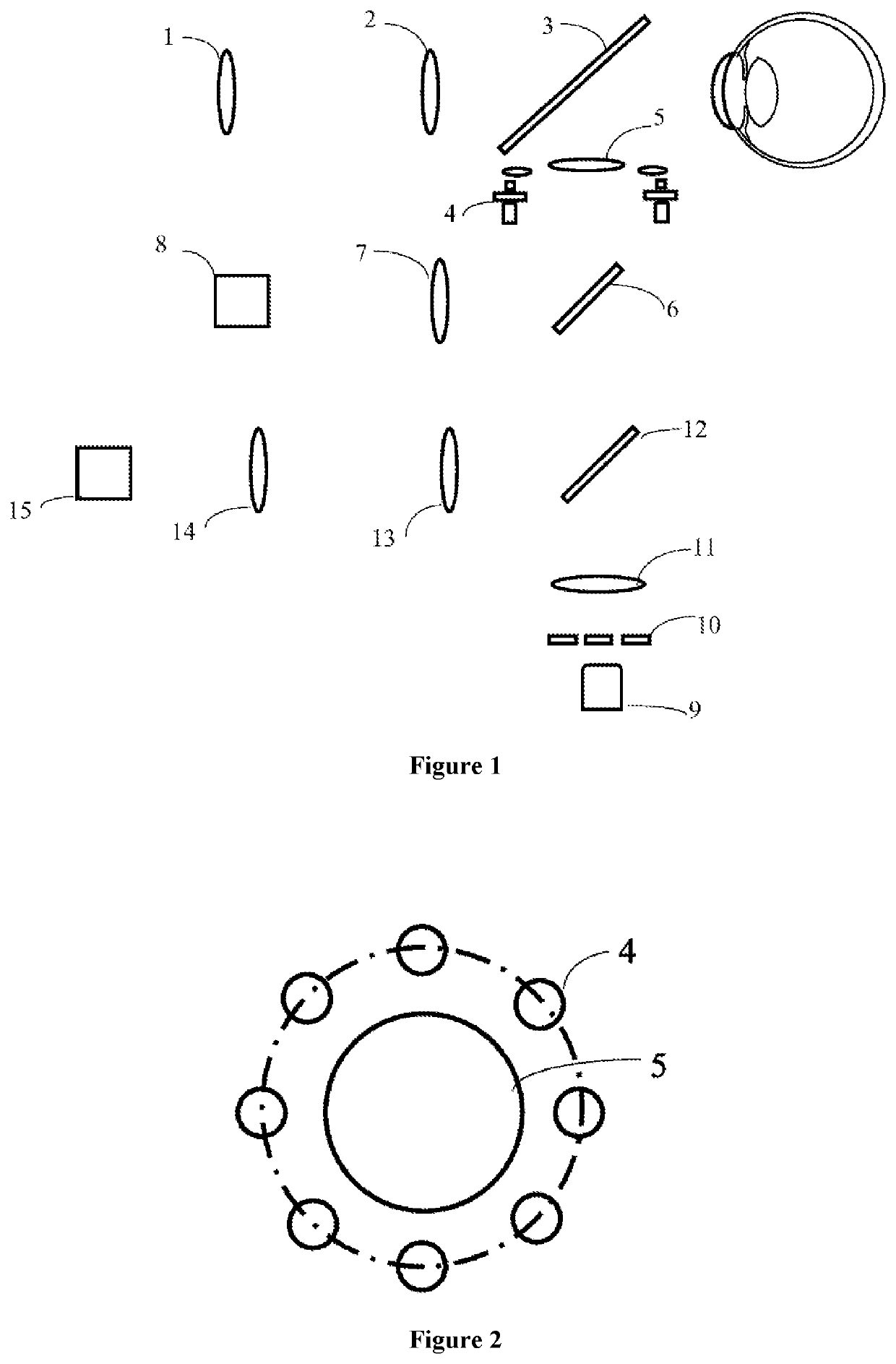
[0035]FIG. 1 shows a hand-held autonomous visual acuity measurement apparatus of the present invention. Combining with FIG. 1, the visual acuity measurement apparatus comprises a first lens group 1, a second lens group 2, a first dichroic mirror 3, a first light source 4, a third lens group 5, a second dichroic mirror 6, a fourth lens group 7, a first image collector 8, a first motor (not shown in the figure), a second light source 9, a diaphragm 10, a seventh lens group 11, a beam splitter 12, a fifth lens group 13, a sixth lens group 14, a second image collector 15 and a second motor (not shown in the figure).

[0036]The first lens group 1 and the second lens group 2 form a fixation vision module for a human eye to gaze at, ...


PUM


Abstract

The present invention discloses a hand-held autonomous visual acuity measurement apparatus and a visual acuity measuring method. The invention comprises a corneal curvature measurement module comprising a first light source for emitting a first light beam and a first image collector for collecting an image formed from the first light beam after it has been reflected by cornea, the first image collector being movably provided in the corneal curvature measurement optical path of the corneal curvature measurement module, and the corneal curvature measurement module further comprises a first motor for driving the first image collector to move along the corneal curvature measurement optical path so that the first image collector moves to the imaging position. Employing the first motor to drive the first image collector to automatically focus, requires no assistance from a second person to adjust the focus, and the subject may complete the vision measurement by oneself, the present invention has capability of being operated by one subject, and convenient visual acuity measurement, and can effectively achieve miniaturization and portability of optometry systems.

Description

CROSS REFERENCE TO RELATED APPLICATIONS[0001]This application is a § 371 National Stage Application of PCT / CN2016 / 095558 filed Aug. 16, 2016, which claims priority to CN201510340549.X filed Jun. 18, 2015, which are hereby incorporated by reference in their entirety.TECHNICAL FIELD OF THE INVENTION[0002]The present invention relates to a hand-held autonomous visual acuity measurement apparatus and a visual acuity measuring method.BACKGROUND OF THE INVENTION[0003]At present, the traditional optometry instruments have a large volume, and are not portable. And, it requires the user have certain professional knowledge, or it needs the professional optometrist to measure the visual acuity of the subject, and the subject cannot independently complete the visual acuity measurement. The working principle of traditional optometry instrument is: the subject fixes the fixed optotype inside (or outside) the instrument, and the measurement crew operates the three-dimensional joystick of the optom...

Claims


Application Information

Patent Timeline
Patent Type & Authority Patents(United States)
IPC IPC(8): A61B3/028A61B3/103A61B3/00A61B3/14A61B3/107
CPCA61B3/028A61B3/0091A61B3/107A61B3/14A61B3/103
Inventor XIE, PEIJIANG, QINCHU, RENYUANZHOU, XINGTAOWANG, QINMEIZENG, JUNWENWEI, RUIHUASHEN, JI
Owner SUZHOU SIHAITONG INSTR
Why Eureka
Try Eureka