Self-service eyesight testing device

A vision measurement, self-service technology, used in eye testing equipment, medical science, diagnosis, etc., can solve the problems of easy arm soreness, decreased vision, difficult vision measurement, etc., to prevent arm soreness and reduce labor intensity.

Inactive Publication Date: 2019-03-01
枣庄市立医院
View PDF5 Cites 5 Cited by
  • Summary
  • Abstract
  • Description
  • Claims
  • Application Information

AI Technical Summary

Problems solved by technology

[0002] Because the mobile phone will emit radiation, so people watching the mobile phone for a long time will cause damage to the eyes, which will lead to vision loss. In a fixed position, the medical staff point their fingers at the visual acuity test chart to measure people's vision. People tend to have so...

Method used


Image

  • Self-service eyesight testing device
  • Self-service eyesight testing device

Examples


Embodiment 1

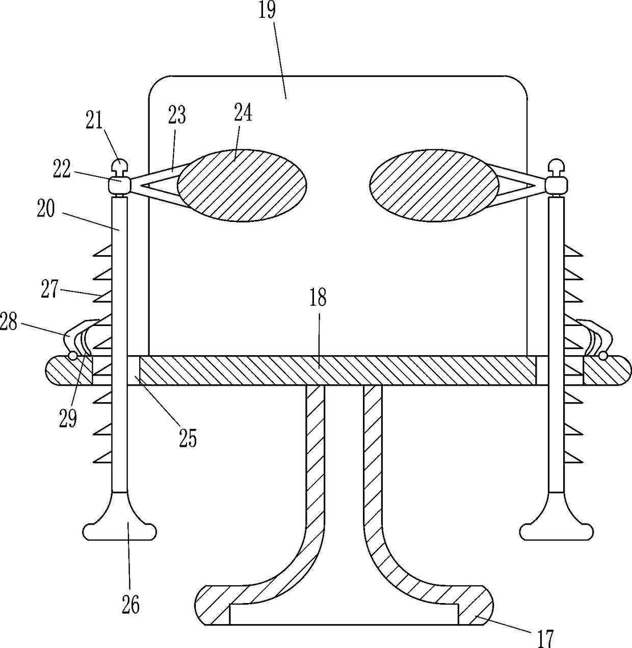
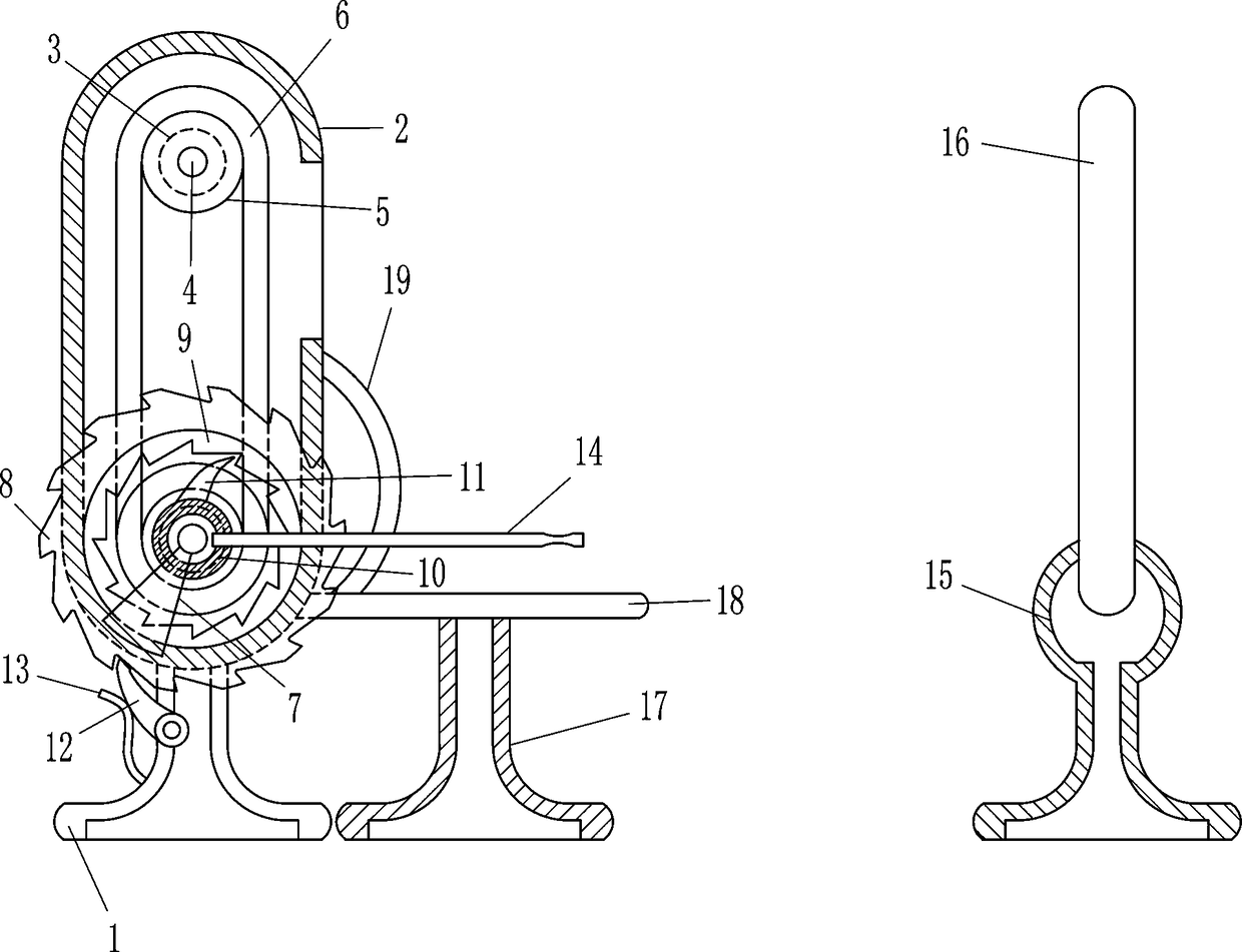
[0018] A self-service vision measuring device, such as Figure 1-2 As shown, it includes a left support 1, an installation frame 2, a bearing seat 3, a rotating rod 4, a roller 5, an eye chart 6, a connecting block 7, an outer ratchet 8, an inner ratchet 9, an annular plate 10, and a soft pawl 11 , swing ratchet 12, elastic pressing sheet 13, swing bar 14, right support 15 and plane mirror 16, the top of left support 1 is connected with mounting frame 2, and the upper front and rear sides in the mounting frame 2 are all equipped with bearing seats 3. Bearing housings 3 are also installed on the front and rear sides of the lower part of the installation frame 2. A rotating rod 4 is connected between the front and rear bearing housings 3. A roller 5 is connected to the rotating rod 4, and a roller is wound between the two rollers 5. Eye chart 6, the front part of the lower rotating rod 4 passes through the installation frame 2, the front end of the lower rotating rod 4 is connec...

Embodiment 2

[0020] A self-service vision measuring device, such as Figure 1-2 As shown, it includes a left support 1, an installation frame 2, a bearing seat 3, a rotating rod 4, a roller 5, an eye chart 6, a connecting block 7, an outer ratchet 8, an inner ratchet 9, an annular plate 10, and a soft pawl 11 , swing ratchet 12, elastic pressing sheet 13, swing bar 14, right support 15 and plane mirror 16, the top of left support 1 is connected with mounting frame 2, and the upper front and rear sides in the mounting frame 2 are all equipped with bearing seats 3. Bearing housings 3 are also installed on the front and rear sides of the lower part of the installation frame 2. A rotating rod 4 is connected between the front and rear bearing housings 3. A roller 5 is connected to the rotating rod 4, and a roller is wound between the two rollers 5. Eye chart 6, the front part of the lower rotating rod 4 passes through the installation frame 2, the front end of the lower rotating rod 4 is connec...

Embodiment 3

[0023] A self-service vision measuring device, such as Figure 1-2 As shown, it includes a left support 1, an installation frame 2, a bearing seat 3, a rotating rod 4, a roller 5, an eye chart 6, a connecting block 7, an outer ratchet 8, an inner ratchet 9, an annular plate 10, and a soft pawl 11 , swing ratchet 12, elastic compression piece 13, swing bar 14, right support 15 and plane mirror 16, the top of left support 1 is connected with mounting frame 2, and the upper front and rear sides in mounting frame 2 are all equipped with bearing seats 3. Bearing housings 3 are also installed on the front and rear sides of the lower part of the installation frame 2. A rotating rod 4 is connected between the front and rear bearing housings 3. A roller 5 is connected to the rotating rod 4, and a roller is wound between the two rollers 5. Eye chart 6, the front part of the lower rotating rod 4 passes through the installation frame 2, the front end of the lower rotating rod 4 is connect...


PUM


Abstract

The invention relates to an eyesight testing device, and in particular relates to a self-service eyesight testing device. The invention aims at providing the self-service eyesight testing device whichcan prevent the ache of the arms and alleviate the labor intensity. The technical scheme is as follows: the self-service eyesight testing device comprises a left support base, a mounting frame, bearing blocks, rotation rods, rollers, a visual chart, a connecting block, an outer ratchet wheel, an inner ratchet wheel, an annular plate, a flexible catch pawl, a swing catch pawl and the like, whereinthe mounting frame is connected to the top of the left support base, the bearing blocks are mounted on the front and rear sides of the upper part in the mounting frame, the bearing blocks are also mounted on the front and rear sides of he lower part in the mounting frame, and the rotation rods are connected between the front and rear bearing blocks. For the device provided by the invention, a swing rod is downwards moved by hands, then the visual chart rotates clockwise, eyesight testing then can be carried out by observing a plane mirror, liftable rods move vertically for enabling eye-shielding plates to move vertically, and therefore, people do not need to cover the eyes by hands for eyesight testing.

Description

technical field [0001] The invention relates to a visual acuity measuring device, in particular to a self-service visual acuity measuring device. Background technique [0002] Because the mobile phone will emit radiation, so people watching the mobile phone for a long time will cause damage to the eyes, which will cause vision loss. In a fixed position, the medical staff point their fingers at the visual acuity test chart to measure people's vision. People tend to have sore arms when using hand-held eye-covering tools for a long time, and at the same time it will increase the labor intensity of the medical staff. In order to reduce the If the labor intensity is lower, the medical staff will reduce the time for measuring people's eyesight, so it is difficult to measure people's eyesight accurately. Contents of the invention [0003] In order to overcome the shortcoming that people use a hand-held eye-covering tool for visual acuity measurement, and people use a hand-held e...

Claims


Application Information

Patent Timeline
IPC IPC(8): A61B3/032
CPCA61B3/032
Inventor 刘华溢
Owner 枣庄市立医院
Why Eureka
Try Eureka