

Device for controlling variable-pitch vanes in a turbomachine
a technology of variable pitch and turbomachine, which is applied in the direction of machines/engines, mechanical apparatus, liquid fuel engines, etc., can solve the problems of impeded efficiency optimization and fuel saving, and achieve the effect of simple, effective and inexpensiv
- Summary
- Abstract
- Description
- Claims
- Application Information
AI Technical Summary
Benefits of technology
Problems solved by technology
Method used
Image

Examples
Embodiment Construction
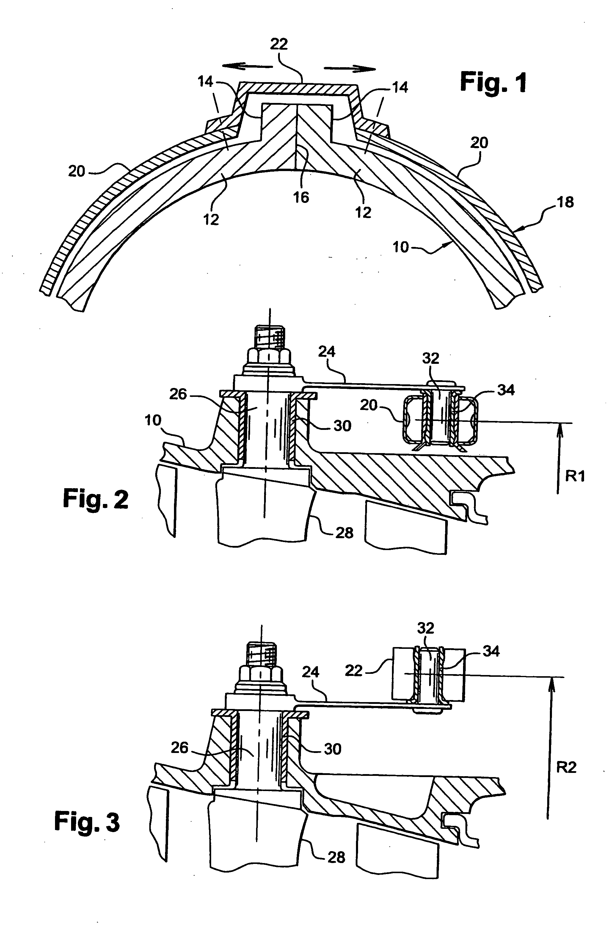
[0025] FIG. 1 is a highly diagrammatic cross-section view showing a portion of a turbomachine casing 10, said casing being made up of two half-shells 12 having longitudinal assembly flanges 14 pressed against each other along a junction plane 16 and projecting outwards from the casing 10.
[0026] A ring 18 for controlling the angular position of variable-pitch vanes surrounds the outside of the casing 10 in the immediate vicinity thereof, and is made up of two approximately semicircular elements which are rigidly interconnected at their ends by two bridges 22, only one of which is shown in FIG. 1, each bridge being placed astride the longitudinal flanges 14 of the casing 10 and allowing the ring 18 to turn to a certain extent about its longitudinal axis, which coincides substantially with the longitudinal axis of the casing 10.
[0027] The means connecting the control ring to a row of variable-pitch vanes are shown diagrammatically in FIGS. 2 and 3.
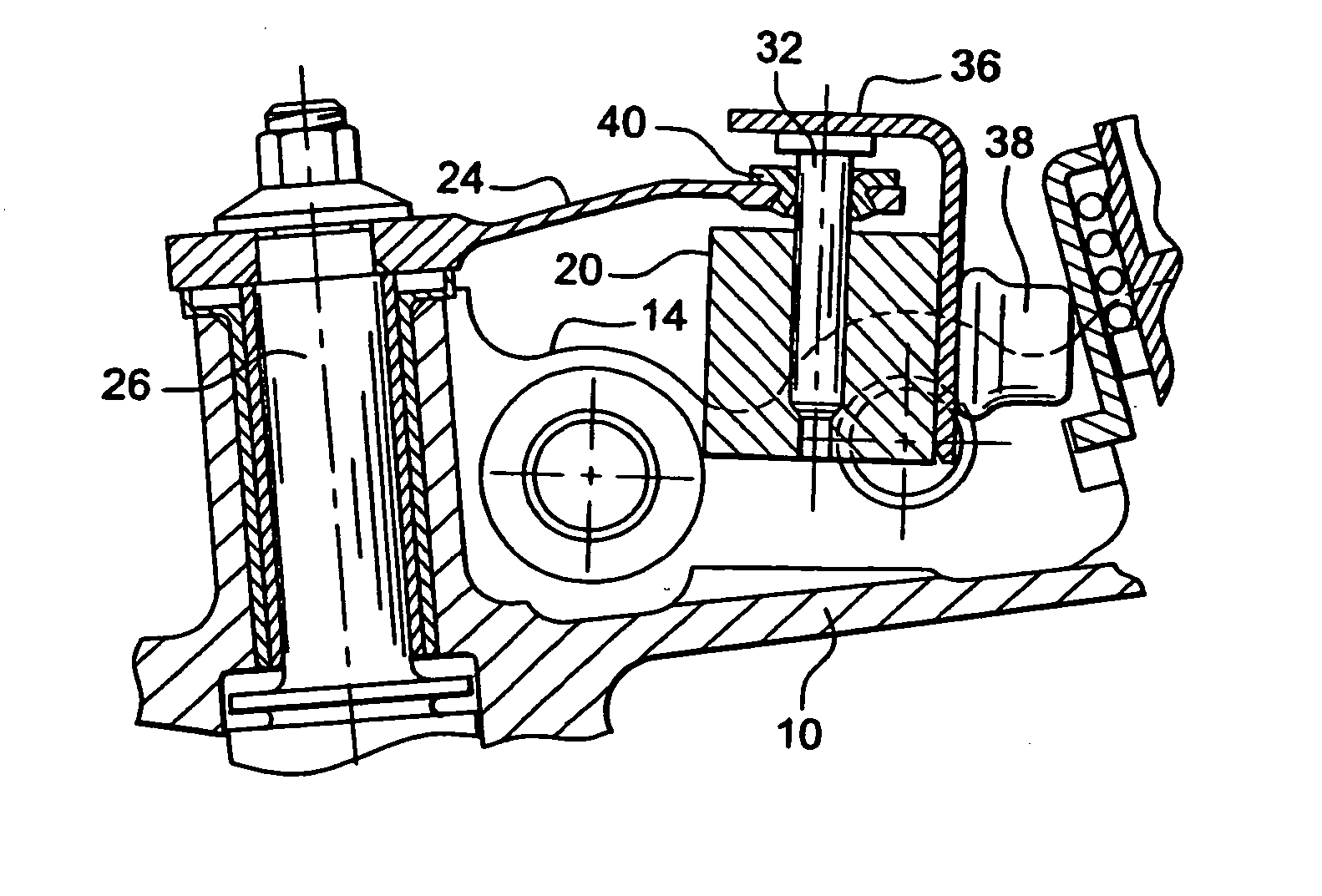
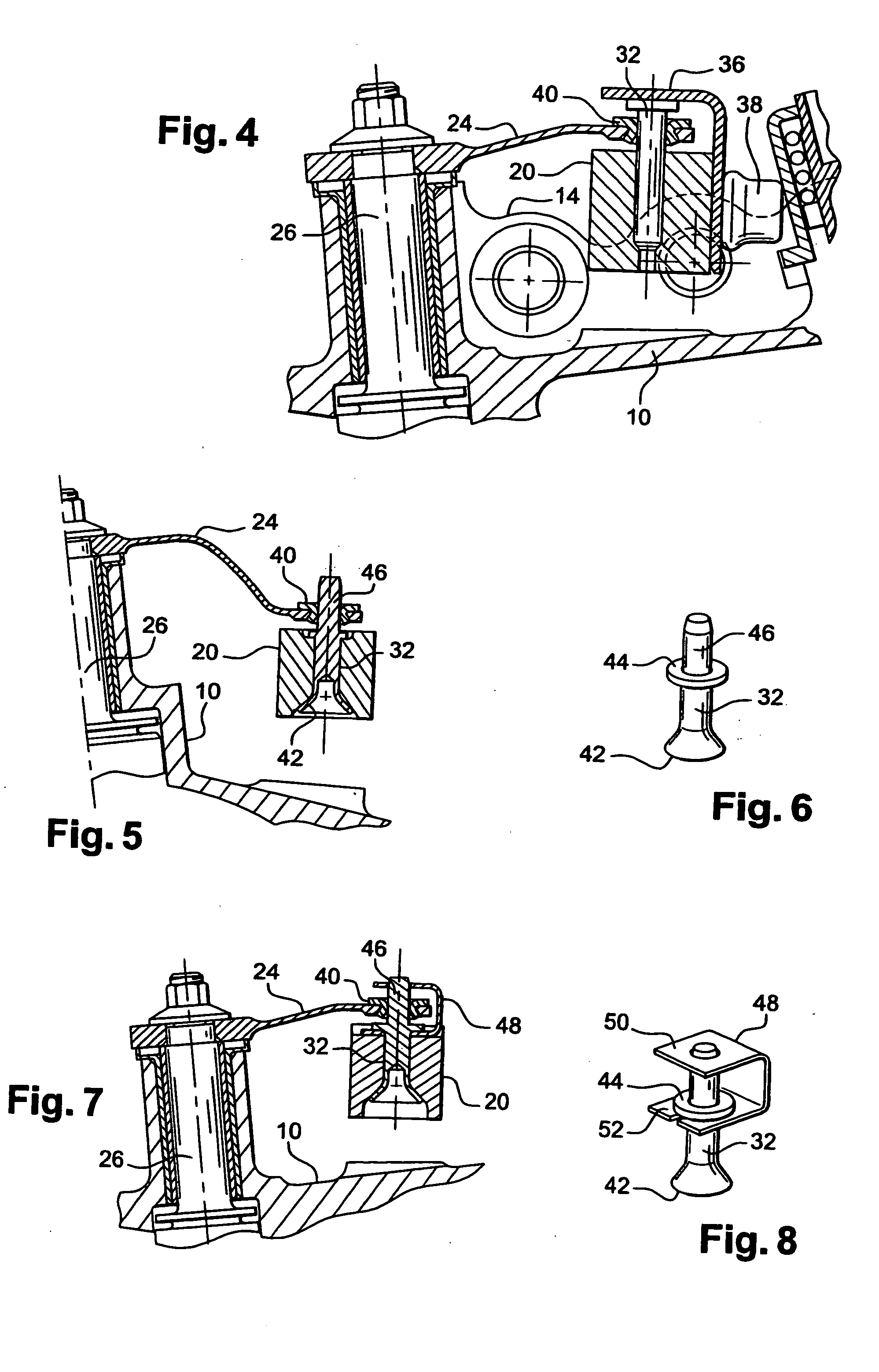
[0028] These means comprise links 24, ...
PUM
 Abstract
Description
Claims
Application Information