Device for checking a turbomachine engine

a turbomachine engine and inspection device technology, applied in the field of turbine engines, can solve the problems of difficult access to certain parts of the turbine engine for known non-destructive inspection devices, and the restricted access zone of the stick, etc., to achieve the effect of simple, effective and inexpensiv

Active Publication Date: 2013-08-06
SN DETUDE & DE CONSTR DE MOTEURS DAVIATION S N E C M A
View PDF14 Cites 11 Cited by
  • Summary
  • Abstract
  • Description
  • Claims
  • Application Information

AI Technical Summary

Benefits of technology

[0010]The invention proposes a solution to the problems of the prior art that is simple, effective, and inexpensive.

Problems solved by technology

Under certain circumstances, such inspection may require the engine to be removed and partially dismantled in order to inspect parts that are difficult to access with inspection means.
Nevertheless, the zone that is accessible to the stick is very limited and generally lies in register with the endoscopic orifice and at a short distance therefrom.
Furthermore, when the probe carried by the stick needs to be used on a part, the probe needs to be pressed against a surface of said part with a certain amount of pressure and for a determined duration, and that is not always possible with the above-mentioned device.
In order to access the wipers of a labyrinth seal, it is therefore necessary to pass the inspection probe into a very narrow space that may present a width or axial dimension of about 1 millimeter (mm), and that is not possible with the above-mentioned stick.
As a result, certain zones of a turbine engine remain difficult to access for known non-destructive inspection devices since they are not designed to pass through orifices or passages of small size and through a plurality of consecutive orifices and / or passages that are not in alignment.
Furthermore, while inspecting a part, the probe generally needs to be held stationary relative to the engine, which is difficult with the above-mentioned prior art stick.

Method used


Image

  • Device for checking a turbomachine engine
  • Device for checking a turbomachine engine
  • Device for checking a turbomachine engine

Examples


Embodiment Construction

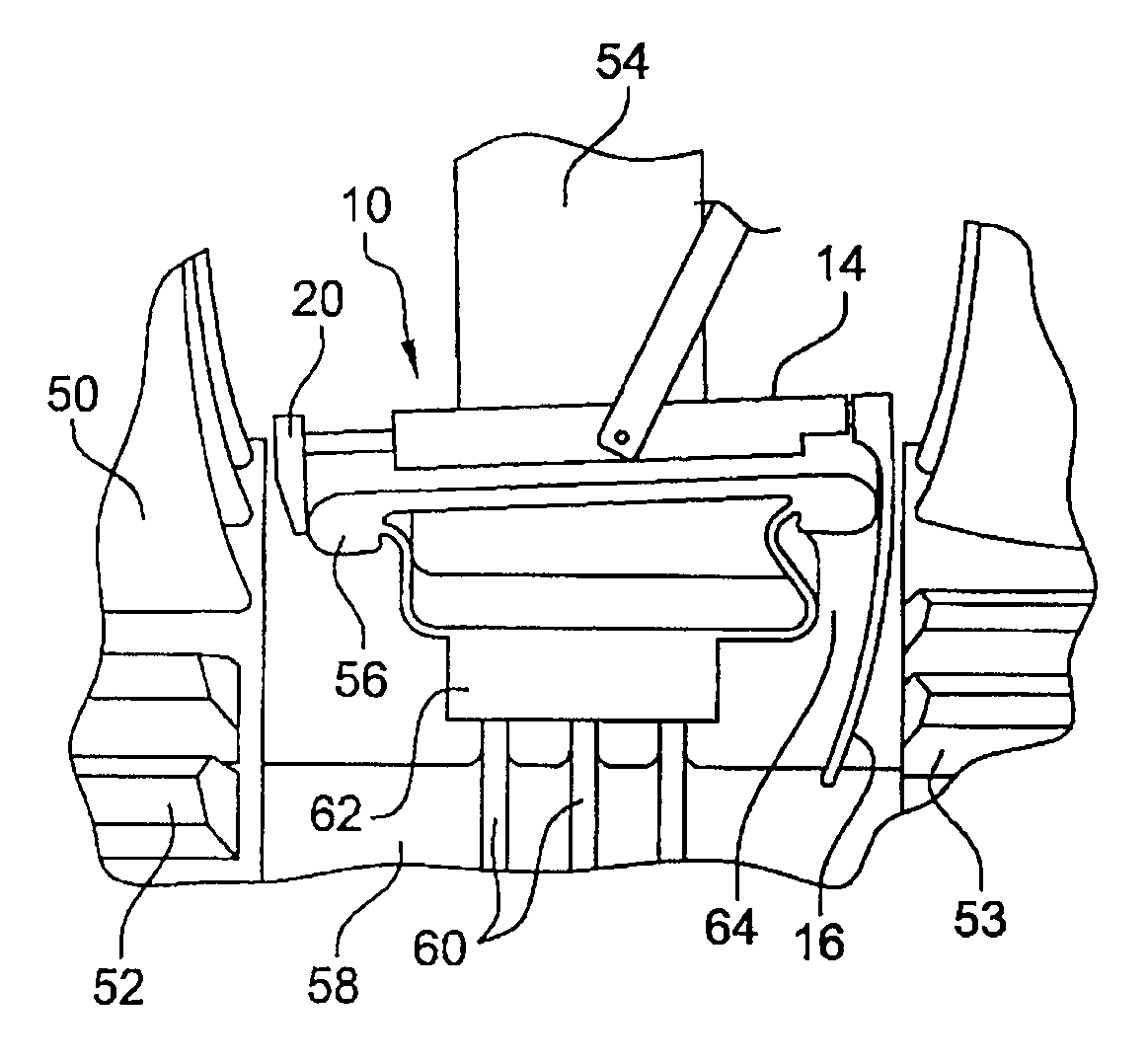
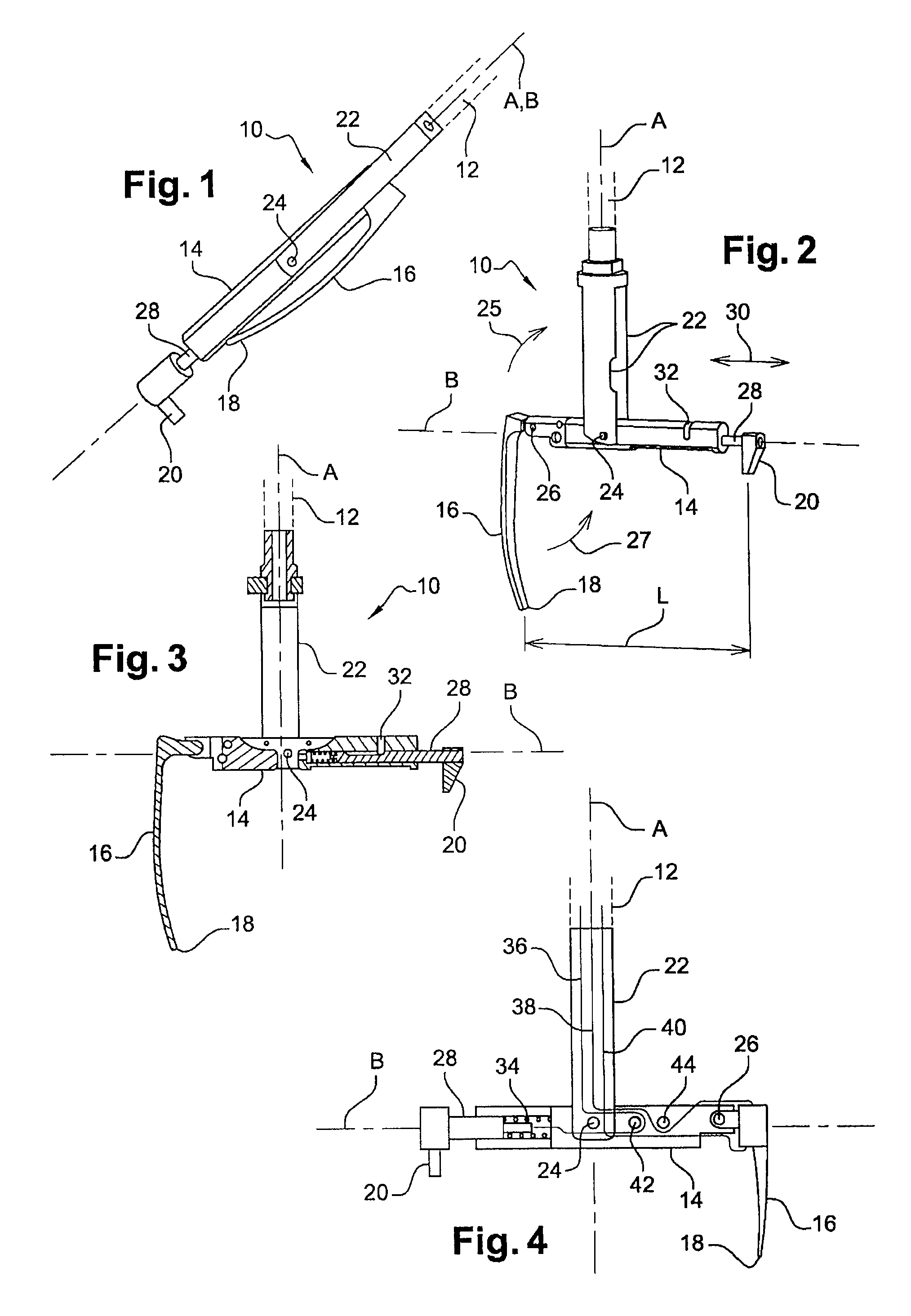
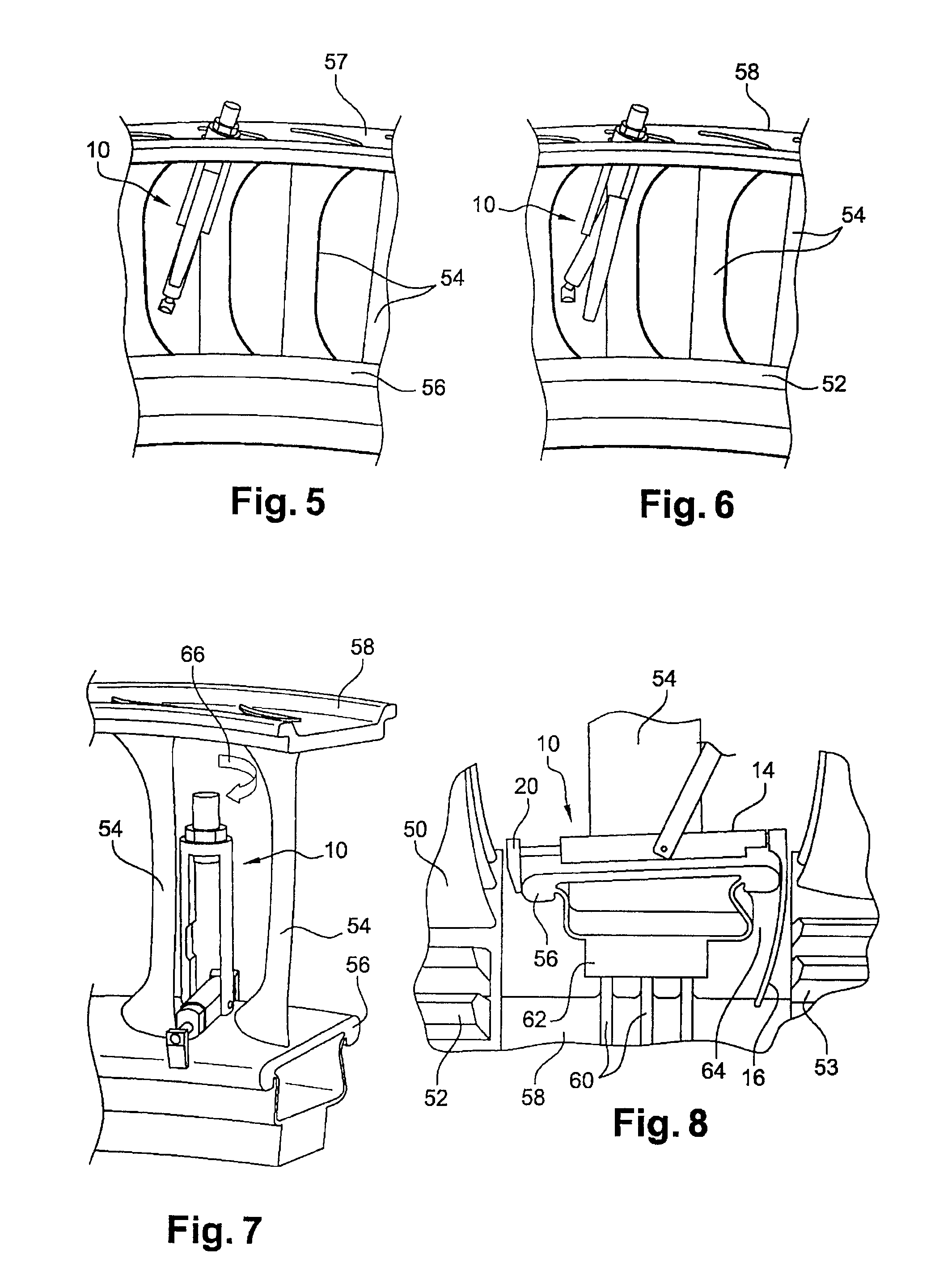
[0028]Reference is made initially to FIGS. 1 to 4 that show a device 10 of the invention for non-destructive inspection of parts of a turbine engine, the engine being described in part below with reference to FIGS. 5 to 8.

[0029]The device 10 comprises a longitudinal stick 12 (shown in dashed lines) having a finger 14 pivotally mounted at the distal end thereof, the finger carrying at one of its ends a blade 16 for supporting an inspection probe 18, and at its opposite end a skid 20 for bearing against and / or catching on an element of the engine.

[0030]The stick 12 carries at its distal end two longitudinal tabs 22 that are parallel and spaced apart, with the finger 14 being pivotally mounted via its middle portion on a pin 24 that extends between the free ends of the tabs 22.

[0031]The finger 14 is movable in pivoting (arrow 25) between a folded position as shown in FIG. 1 in which it extends between the tabs and parallel to the longitudinal axis A of the stick, and a deployed positio...


PUM


Abstract

A device for non-destructive in situ inspection of parts of a turbine engine, the device including a stick carrying at its distal end a pivoting finger carrying at one of its ends a blade for supporting an inspection probe, and at its opposite end a skid for bearing against and/or catching on an element of the engine, the skid being movable in a direction parallel to the longitudinal axis of the finger.

Description

BACKGROUND OF THE INVENTION[0001]1. Field Of The Invention[0002]The present invention relates to a device for non-destructive in situ inspection of parts of an engine, in particular a turbine engine.[0003]2.Description Of The Related Art[0004]Non-destructive inspection (NDI) of parts of a turbine engine serve to verify the state of such parts without damaging them. Under certain circumstances, such inspection may require the engine to be removed and partially dismantled in order to inspect parts that are difficult to access with inspection means.[0005]A known inspection device comprises a rigid stick carrying an inspection probe or a sensor at its distal end. When the turbine engine is fitted with endoscopic orifices, the stick is inserted into the turbine engine through one of these orifices in order to perform in situ inspection of parts of the turbine engine, thereby avoiding any need to remove the engine or to dismantle it.[0006]Nevertheless, the zone that is accessible to the s...

Claims


Application Information

Patent Timeline
Patent Type & Authority Patents(United States)
IPC IPC(8): G01M15/14
CPCG01N27/9033G01N29/07G01N29/24G01N29/223G01N2291/2693G01N27/9006
Inventor GAISNON, PATRICKMISTRAL, QUENTINMOZER, SYLVIESAMAK, NICOLAS
Owner SN DETUDE & DE CONSTR DE MOTEURS DAVIATION S N E C M A
Why Eureka
Try Eureka