Method and tooling for assembling a guide vane stage

a technology of guide vane and tooling, which is applied in the direction of machines/engines, liquid fuel engines, turbines, etc., can solve the problems of difficult reproducibility, long and expensive injection steps, and messy, and achieve the effect of simple, effective and inexpensiv

Active Publication Date: 2017-03-28
SN DETUDE & DE CONSTR DE MOTEURS DAVIATION S N E C M A
View PDF10 Cites 11 Cited by
  • Summary
  • Abstract
  • Description
  • Claims
  • Application Information

AI Technical Summary

Benefits of technology

[0008]The present invention provides a solution to this problem that is simple, effective, and inexpensive.

Problems solved by technology

Resin is injected into the gaps by means of a syringe that is filled by an operator, with this injection step being lengthy and expensive (taking about 8 hours for a single guide vane stage), difficult, messy, and difficult to make reproducible.
Nevertheless, although that makes it easier to put the resin into place, it makes managing batches of resin more complex.

Method used


Image

  • Method and tooling for assembling a guide vane stage
  • Method and tooling for assembling a guide vane stage
  • Method and tooling for assembling a guide vane stage

Examples


Embodiment Construction

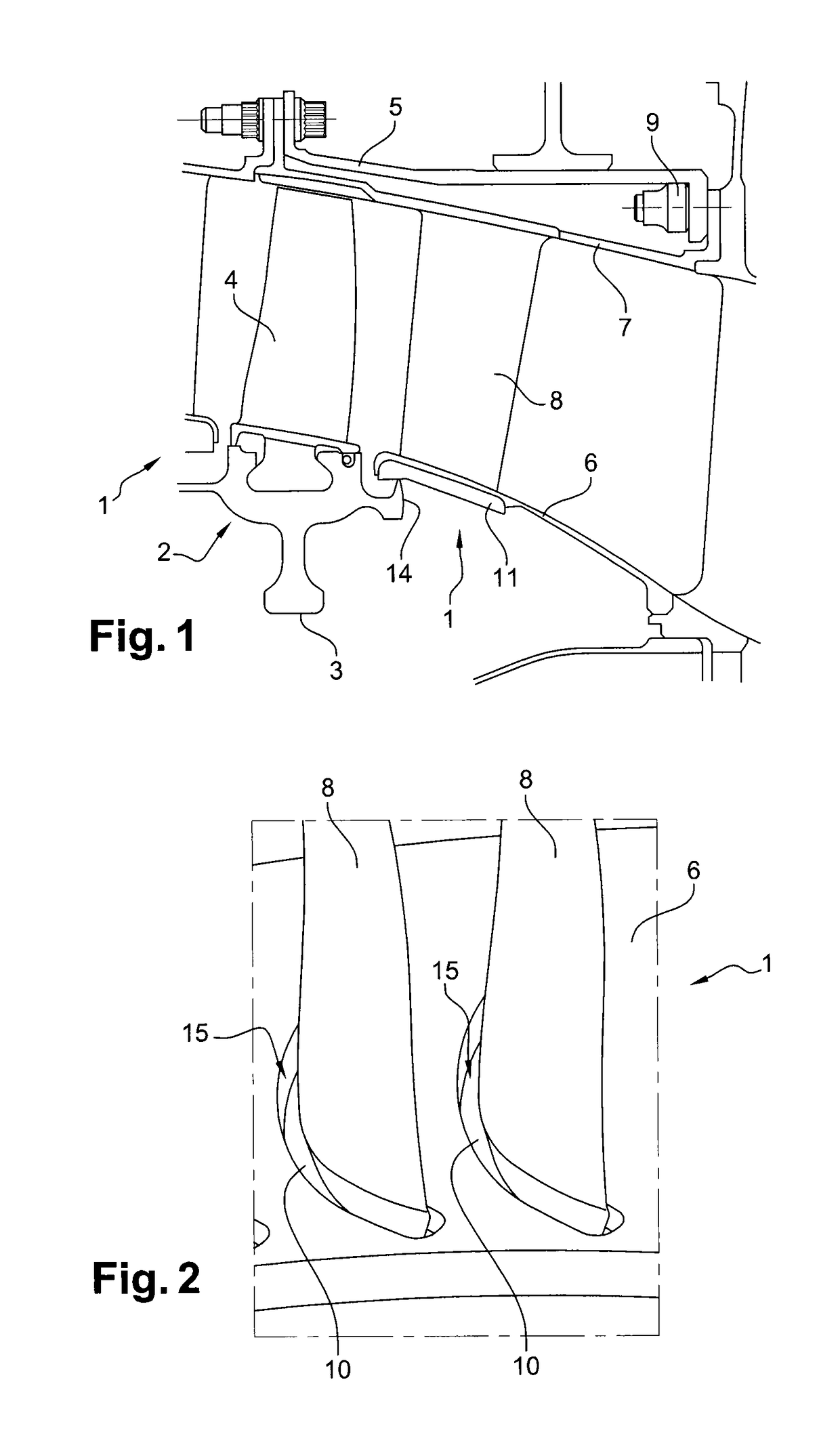
[0036]Reference is made initially to FIG. 1 which shows a low pressure compressor of a turbine engine such as an airplane turboprop or turbojet, the compressor comprising guide vane stages 1 having rotor wheels 2 mounted between them.

[0037]Each rotor wheel 2 comprises a disk 3 carrying an annular row of substantially radial blades 4 at its periphery and surrounded by a compressor casing 5.

[0038]Each guide vane stage 1 comprises two shrouds, respectively an inner shroud 6 and an outer shroud 7, with an annular row of substantially radial airfoils 8 extending between them, the outer shroud 7 being fastened to the casing 5 by nut-and-bolt type means 9.

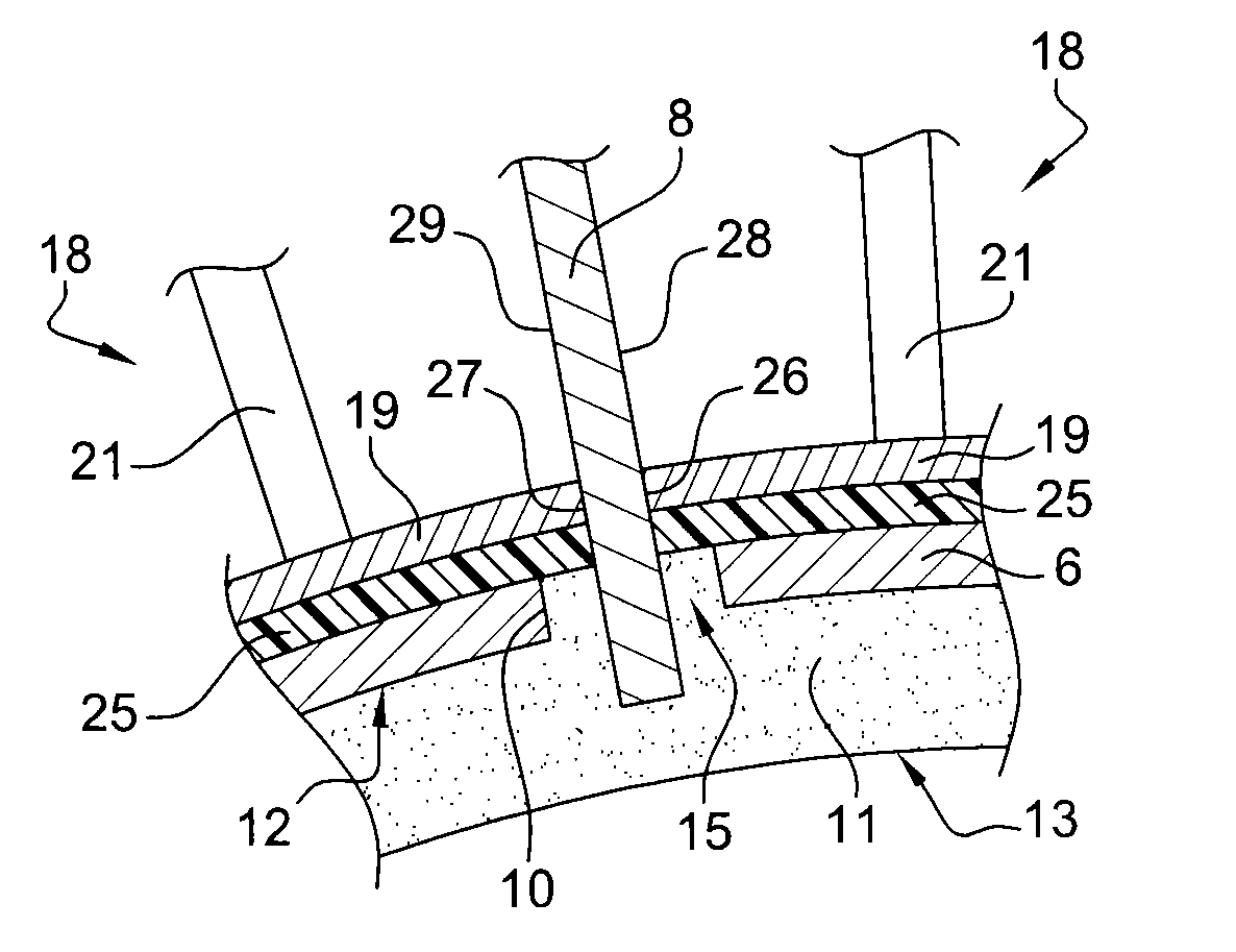
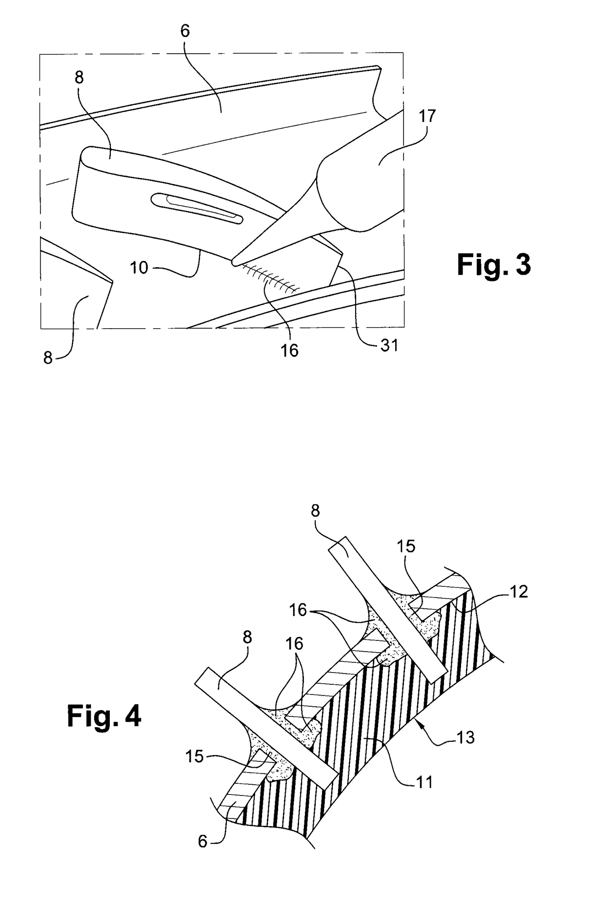
[0039]The radially outer ends of the airfoils are welded to the outer shroud 7. The radially inner ends of the airfoils are engaged, with clearance gaps, in orifices 10 in the inner shroud 6 (FIG. 2) and they are secured to the inner shroud 6 by applying a polymerizable sealing resin 11 to the radially inner surface 12 of the inner shroud...


PUM

PropertyMeasurementUnit
widthaaaaaaaaaa
thicknessaaaaaaaaaa
temperatureaaaaaaaaaa

Abstract

A method and tooling for assembling a guide vane stage that includes an inner shroud and an outer shroud that are coaxial and interconnected by radial airfoils, the method including holding plates pressed against an outer surface of the inner shroud so that the plates cover gaps formed between openings in the inner shroud and the airfoils at least in part and in a manner that is leaktight, and applying a sealing resin to the inner surface of the inner shroud so that the resin fills the gaps and so that radially inner ends of the airfoils are embedded in the resin.

Description

BACKGROUND OF THE INVENTION[0001]Field of the Invention[0002]The present invention relates to a method and to tooling for assembling a guide vane stage, in particular for a low pressure compressor of a turbine engine.[0003]Description of the Related Art[0004]In a turbine engine compressor, a guide vane stage comprises two axial shrouds extending one inside the other and interconnected by substantially radial airfoils that are fastened via their radial ends to the shrouds.[0005]The outer shroud of the guide vane stage has radial orifices in which the radially outer ends of the airfoils are engaged and fastened, generally by welding. The inner shroud includes radial orifices in which the radially inner ends of the airfoils are engaged with clearance gaps, these gaps presenting a width lying in the range 2 millimeters (mm) to 3 mm, approximately.[0006]In the prior art, the inner ends of the airfoils are secured to the inner shroud by means of a polymerizable sealing resin that is appli...

Claims


Application Information

Patent Timeline
Patent Type & Authority Patents(United States)
IPC IPC(8): F01D25/28B23K31/02B23P6/00F01D9/04
CPCF01D25/285B23K31/02B23P6/002F01D9/04F01D9/044B23K2201/001F05D2230/60F05D2230/64Y10T29/49323Y10T29/53913B23K2101/001F04D29/542
Inventor CHARDONNET, ROMAIN RENE MARCELPETIT, PATRICK GILBERTMARTINEZ, ALAIN
Owner SN DETUDE & DE CONSTR DE MOTEURS DAVIATION S N E C M A
Why Eureka
Try Eureka