Turbojet having a large bypass ratio

a technology of bypass ratio and turbine, which is applied in the direction of machines/engines, gas turbine plants, spraying apparatuses, etc., can solve the problems of reducing the clearance between the casing and the rotor at some locations, increasing the clearance, and deformation of the casing, so as to increase the in-flight idle speed and increase the thrust of the turbojet

Active Publication Date: 2005-08-11
SN DETUDE & DE CONSTR DE MOTEURS DAVIATION S N E C M A
View PDF16 Cites 11 Cited by
  • Summary
  • Abstract
  • Description
  • Claims
  • Application Information

AI Technical Summary

Benefits of technology

[0014] This characteristic of the invention presents a particular advantage when the operability of the turbojet makes it necessary to increase the in-flight idling speed during the descent and approach stages of the airplane. This increase in speed increases the thrust from the turbojet which becomes too high. The flaps provided on the jacket serve to spoil the thrust delivered by the secondary flow during the descent and approach stages, thereby bringing the total thrust down to an appropriate level.
[0015] It then becomes possible in a high bypass ratio turbojet to envisage eliminating the conventional thrust reversal system.

Problems solved by technology

Bending deformations of the turbojet body in turn lead to deformations of the casing around the rotor, with the casing ovalizing, which reduces the clearance between the casing and the rotor at some locations while increasing the clearance at other locations (the “casing distortion” effect).

Method used


Image

  • Turbojet having a large bypass ratio
  • Turbojet having a large bypass ratio
  • Turbojet having a large bypass ratio

Examples


Embodiment Construction

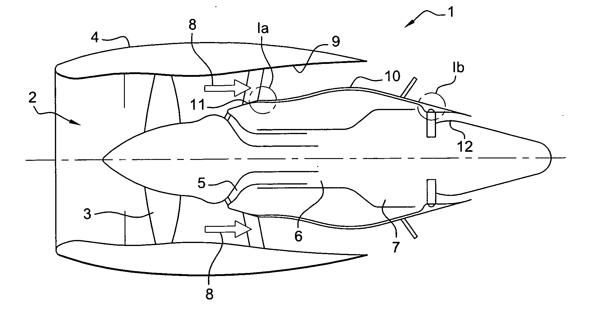
[0022]FIG. 1 is a highly diagrammatic view of a bypass turbojet 1 having, at its front end, a fan 2 comprising a wheel 3 that revolves inside a shroud 4. The flow of air sucked in by the fan 2 is split downstream from the fan into a main flow which passes through an engine comprising a compressor 5, an annular combustion chamber 6, and a turbine 7, and a bypass flow which flows around the engine as shown by arrows 8 and which provides additional thrust over and above the thrust provided by the combustion gas exhausted from the turbine 7.

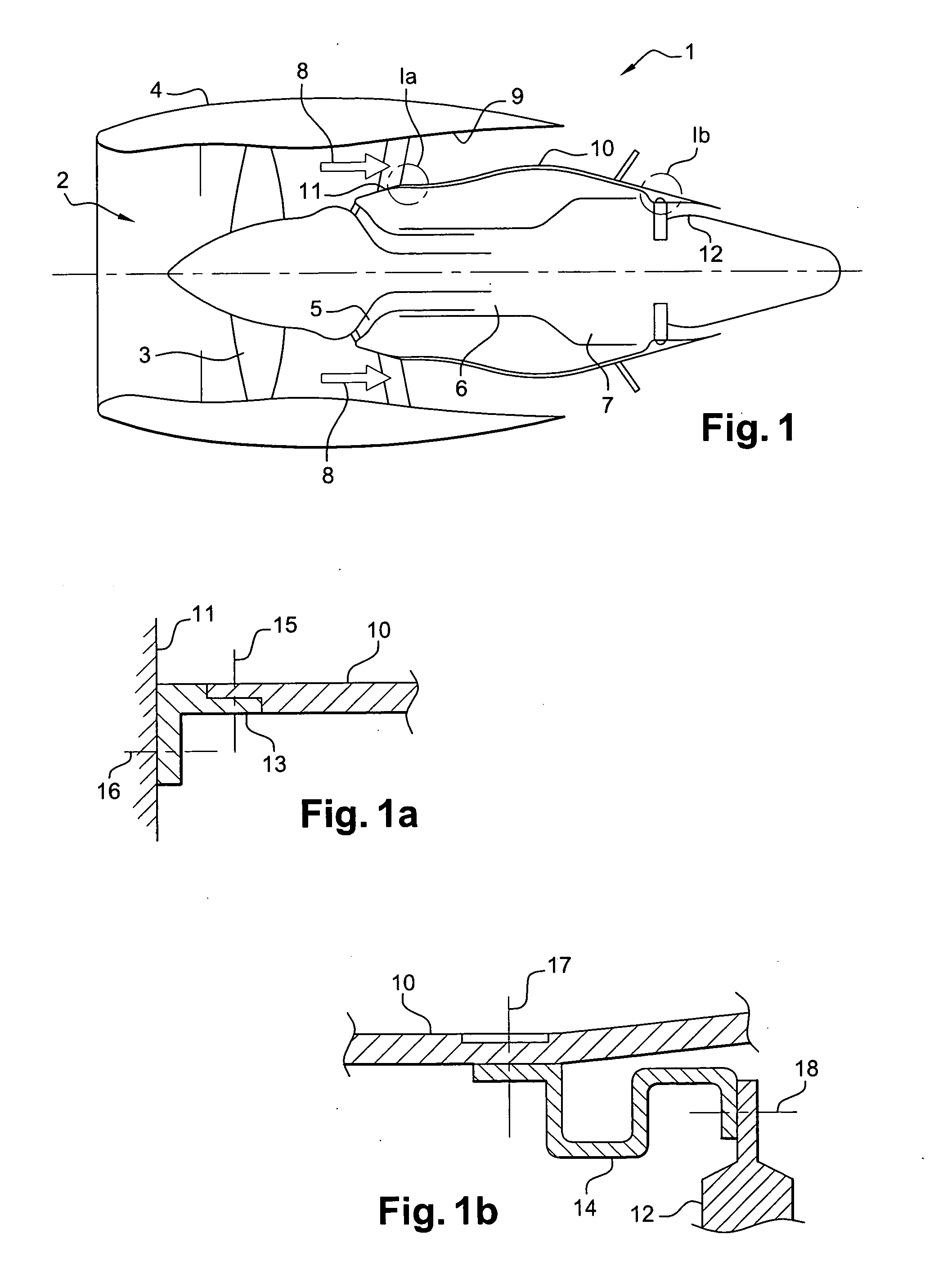
[0023] The path for the bypass flow 8 is defined on its outside by the inside wall 9 of the shroud, and on its inside by a jacket 10 of substantially cylindrical shape that surrounds the engine and that extends from a structural casing, such as an intermediate casing 11, to an exhaust casing 12 at the outlet from the turbine. The intermediate casing 11 is rigidly connected by radial arms to the fan shroud.

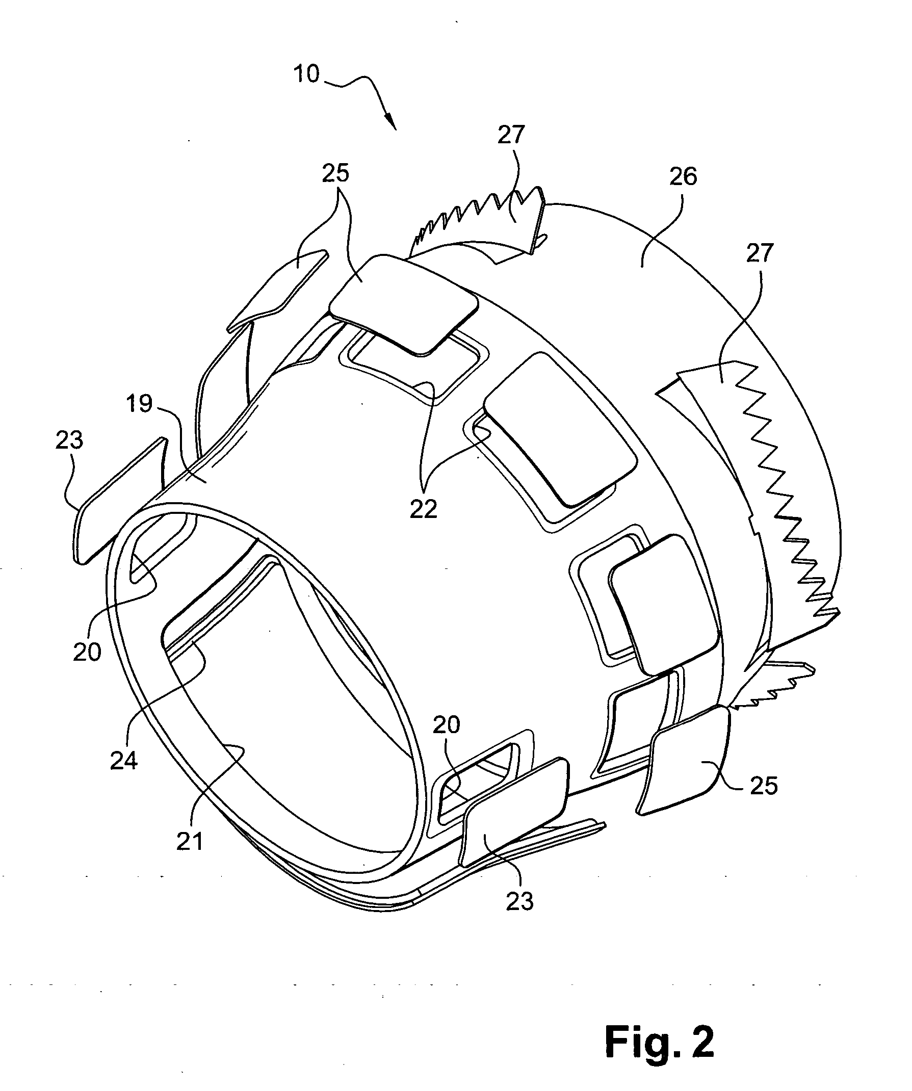
[0024] According to the invention, the jack...


PUM


Abstract

A turbojet comprises at least a fan, a compressor, a combustion chamber, a turbine, and a rigid substantially-cylindrical jacket fastened at its upstream end to an intermediate casing and at its downstream end to an exhaust casing, the jacket serving to transmit forces between the intermediate casing and the exhaust casing.

Description

[0001] The invention relates to a turbojet, in particular a turbojet having a large bypass ratio, the turbojet comprising at least one compressor, a combustion chamber, a turbine, and a fan mounted upstream from the compressor and rotated by the turbine, and means downstream from the fan defining an annular space for a bypass flow to flow around the casings of the compressor, the combustion chamber, and the turbine, which bypass flow adds to the combustion gas of the main flow in order to increase thrust. BACKGROUND OF THE INVENTION [0002] The turbojets of modern civil airplanes are characterized by a large bypass ratio, i.e. a ratio of bypass flow divided by main flow that is greater than 5, and that may be as great as 9 or 10. This leads to a reduction in the transverse dimensions of the body of the turbojet between the fan and the turbine (the “wasp waist” effect), and this reduction in transverse dimensions leads to a reduction in the bending strength of said body. [0003] Bendin...

Claims


Application Information

Patent Timeline
Patent Type & Authority Applications(United States)
IPC IPC(8): F01D25/24F01D5/22F02C7/00F02C7/20F02K1/68F02K1/70F02K3/06
CPCF02C7/20F05D2240/14F01D5/22F02K1/68
Inventor BEUTIN, BRUNODOS SANTOS, NELSONFERT, JEREMYLACORRE, FABIENNEPICARD, JEAN-LOUIS
Owner SN DETUDE & DE CONSTR DE MOTEURS DAVIATION S N E C M A
Why Eureka
Try Eureka