Apparatus and method for image forming capable of performing an improved image fixing using a cooler

Inactive Publication Date: 2005-01-13
RICOH KK
View PDF14 Cites 13 Cited by
  • Summary
  • Abstract
  • Description
  • Claims
  • Application Information

AI Technical Summary

Benefits of technology

[0010] In view of the foregoing, it is an object of the present invention to provide a novel image forming apparatus capable of preventing toner offset.
[0011] Another object of the present invention is to provide a novel fixing device capable of preventing toner offset.
[0012] Another object of the present invention is to provide a novel image forming method for preventing toner offset.
[0013] Another object of the present invention is to provide a novel image fixing method for preventing toner offset.
[0014] To achieve the above and other objects, in one example, an image forming apparatus includes an image forming mechanism and a fixing device. The fixing device includes a fixing rotator, a pressure rotator, at least one cleaning roller, at least one detector, and a cooler. The fixing rotator and the pressure rotator closely contact with each other. The at least one cleaning roller closely contacts with at least one of the fixing rotator and the pressure rotator. The at least one detector detects a surface temperature of at least one of the fixing rotator, the pressure rotator, and the cleaning rotator. The cooler lowers the surface temperature of the at least one cleaning roller based on the detected surface temperature.

Problems solved by technology

The toner adhered to the surface of the fixing roller may be then transferred back to the transfer sheet (the so-called “toner offset”), thereby deteriorating the image quality.
However, the toner has such a high glass transition temperature that an image needs to be fixed at a high temperature.
Thus, high-speed image forming or energy saving may not be easily attained.
In practice, however, the toner containing a polyester resin tends to melt at a lower temperature, thereby causing the toner offset problem more easily.
Such a background image forming apparatus successfully prevents toner offset, however, it suffers from a lower productivity.
In addition, the background image forming apparatus fails to completely eliminate the toner offset when a toner containing a polyester resin is used.

Method used


Image

  • Apparatus and method for image forming capable of performing an improved image fixing using a cooler
  • Apparatus and method for image forming capable of performing an improved image fixing using a cooler
  • Apparatus and method for image forming capable of performing an improved image fixing using a cooler

Examples


Embodiment Construction

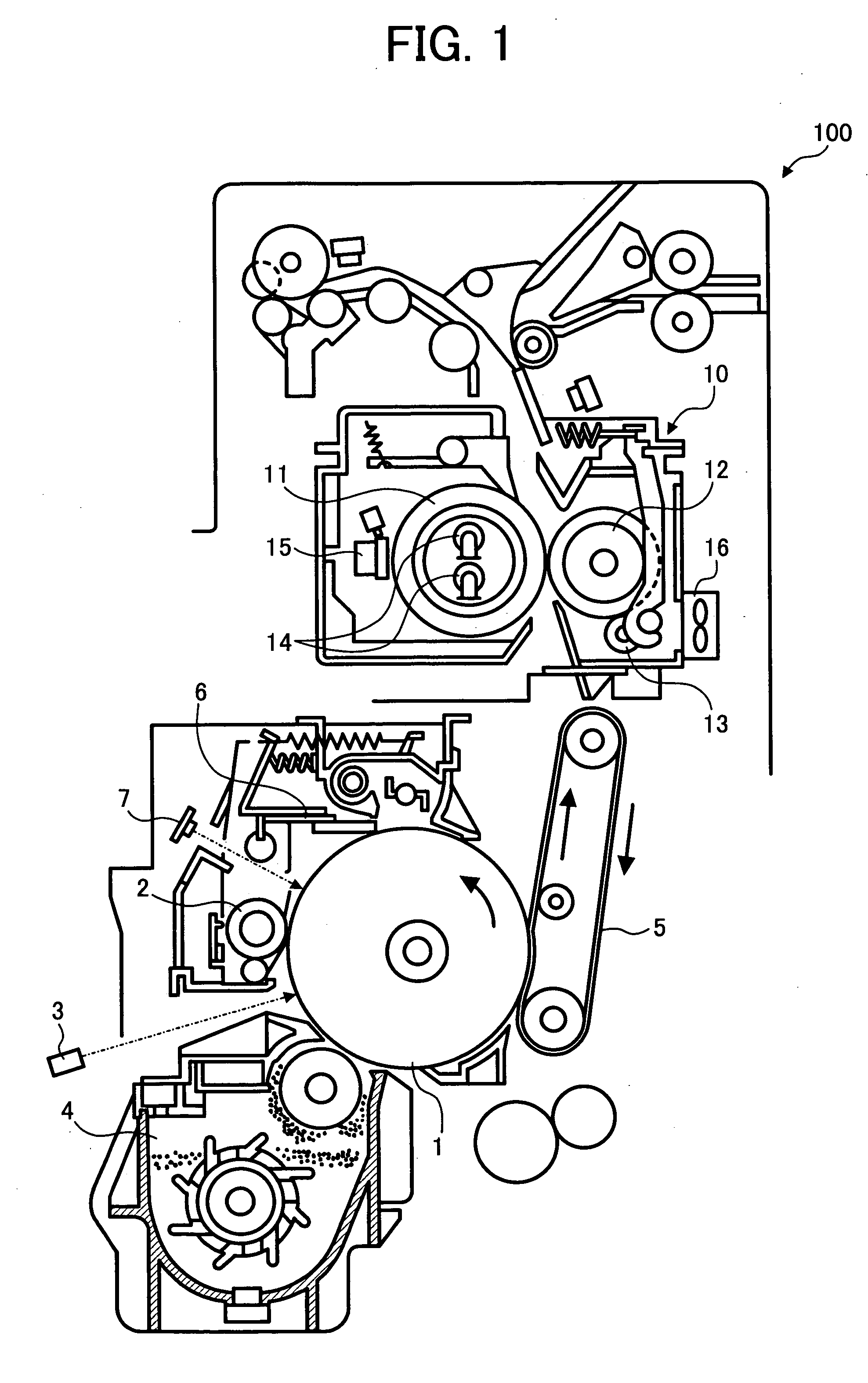
[0029] In describing preferred embodiments illustrated in the drawings, specific terminology is employed for the sake of clarity. However, the disclosure of this patent specification is not intended to be limited to the specific terminology so selected and it is to be understood that each specific element includes all technical equivalents that operate in a similar manner. Referring now to the drawings, wherein like reference numerals designate identical or corresponding parts throughout the several views, particularly to FIG. 1, an image forming apparatus 100 according to an exemplary embodiment of the present invention is explained.

[0030] In FIG. 1, a photoconductor 1 rotates in a counterclockwise direction as indicated by an arrow. Around the photoconductor 1 are arranged a charging device 2, an exposure device 3, a developing device 4, a transfer device 5, a cleaning device 6, a discharging device 7, and the fixing device 10.

[0031] The charging device 2 uniformly charges the s...


PUM


Abstract

An image forming apparatus capable of preventing toner offset is disclosed that includes an image forming mechanism and a fixing device. The fixing device includes a fixing rotator, a pressure rotator, a cleaning roller, a temperature detector, and a cooler. The temperature detector detects a surface temperature of at least one of the fixing rotator, the pressure rotator, and the cleaning roller. The cooler operates based on the temperature detected by the temperature detector. An image forming method and an image fixing method are also described.

Description

CROSS-REFERENCE TO RELATED APPLICATIONS [0001] This patent specification is based on Japanese patent application No. JPAP2003-133329, filed on May 12, 2003 in the Japanese Patent Office, the entire contents of which are incorporated by reference herein. BACKGROUND OF THE INVENTION [0002] 1. Field of the Invention [0003] The present invention relates to an apparatus and method for image forming, and more particularly to an apparatus and method for image forming capable of preventing toner offset in an image fixing by using a cooler. [0004] 2. Discussion of the Background [0005] In a background image forming apparatus using Electrophotography such as a copier, a printer, and a facsimile, an image is formed through various steps including charging, exposing, developing, transferring, fixing, cleaning, and discharging. [0006] In the fixing step, a toner image is generally fixed to a transfer sheet by heating and pressing the toner image using a fixing roller and a pressure roller. Howev...

Claims


Application Information

Patent Timeline
IPC IPC(8): G03G9/08G03G9/087G03G15/20G03G21/20
CPCG03G15/2025
Inventor KARASAWA, KAZUNORI
Owner RICOH KK
Why Eureka
Try Eureka