Container and method for measuring and mixing micro and macro amounts

a micro- and macro-sized technology, applied in the field of containers, can solve the problems of difficult to perform this task with a typical bucket, and difficult to make this measurement, and achieve the effect of improving the accuracy of the measurement results

Inactive Publication Date: 2005-01-20
LYON MARK DAMON
View PDF18 Cites 50 Cited by
  • Summary
  • Abstract
  • Description
  • Claims
  • Application Information

AI Technical Summary

Benefits of technology

[0009] The present invention is a container where macro measurements can be made using the graduations on the sidewall, but with the added feature that micro measurements can be made as well. This is done by either 1). Using supplemental measurement depressions of various capacities formed into the bottom of the container or by 2). Using a single supplemental measurement depression that has graduations on the depression wall or by 3). Using graduations on the bottom and / or sidewall when the container is reoriented or by 4). Attaching an auxiliary measuring device for the micro measurements to the inside of an existing container. Prior to the present invention, in order to mix one cup of bleach with one gallon of water in a bucket, one would first have to obtain a measuring cup, pour the bleach into the measuring cup, pour the measuring cup into the bucket, fill the bucket with one gallon of water using the graduations on the bucket's sidewall for reference, then lastly, rinse out the measuring cup. Alternatively, with the present invention in its preferred embodiment, one would pour the bleach directly into the segments in the bottom of the bucket until one cup is reached, then lastly, fill the bucket with one gallon of water using the graduations on the sidewall for reference. With the present invention, the steps of having to find, use and rinse out a measuring cup are eliminated.

Problems solved by technology

Performing this task with a typical bucket is very difficult given the manner in which the measurement graduations appear on the sidewall.
It would be very difficult to make this measurement.

Method used


Image

  • Container and method for measuring and mixing micro and macro amounts
  • Container and method for measuring and mixing micro and macro amounts
  • Container and method for measuring and mixing micro and macro amounts

Examples


embodiment 1

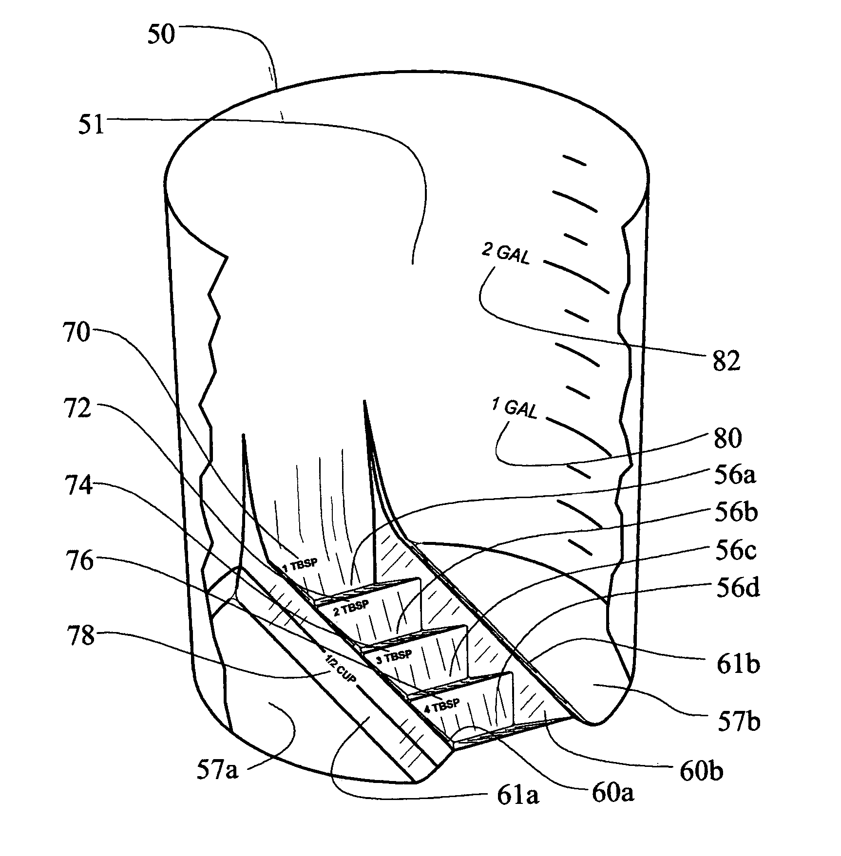
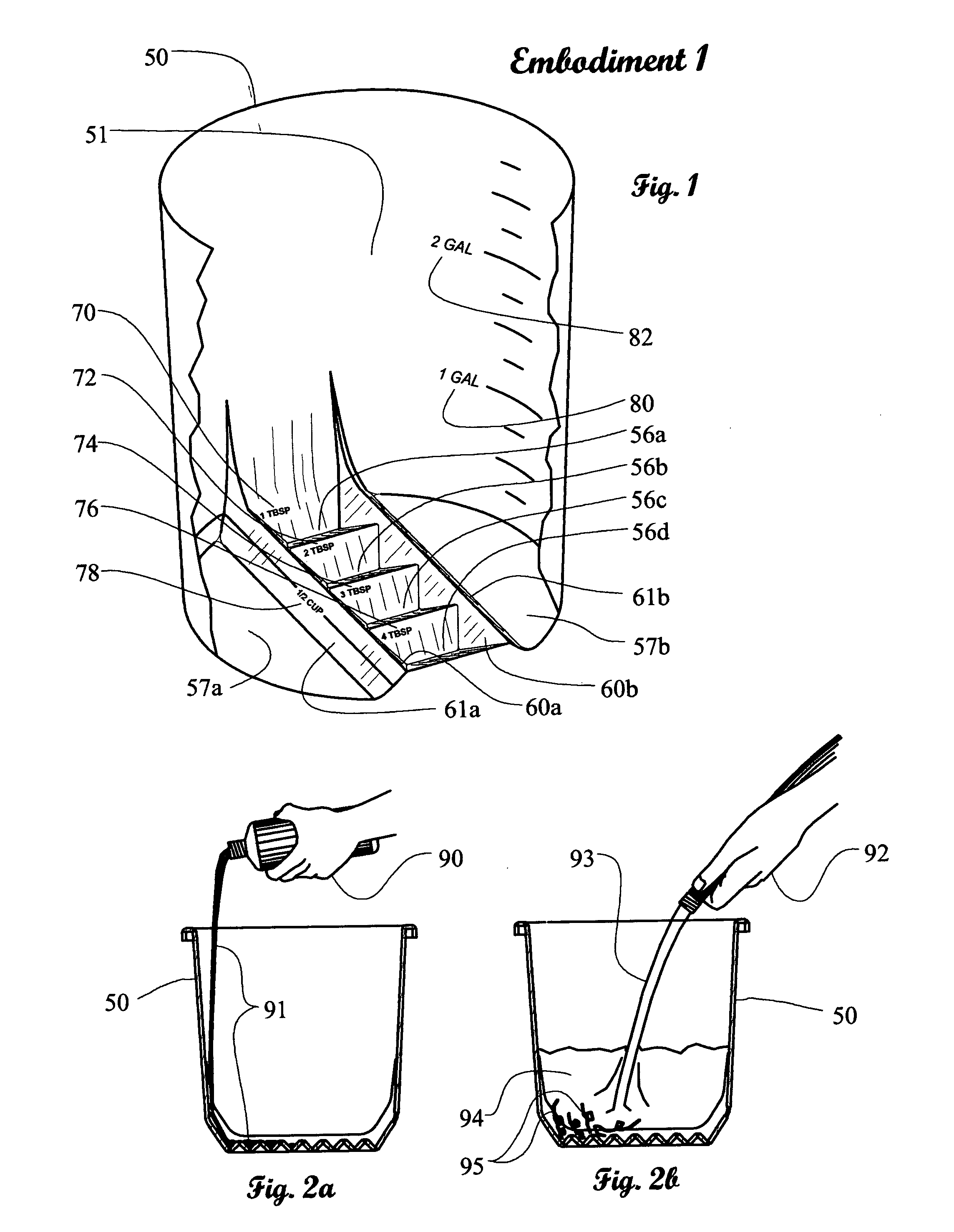
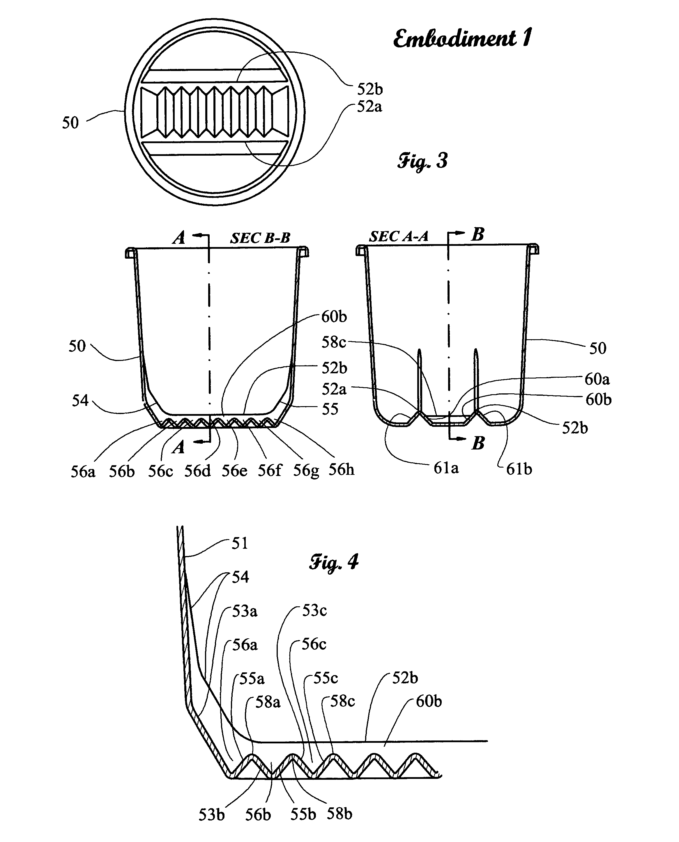
[0033] Embodiment 1, FIG. 1, shows a container 50 similar to a household bucket but with novel alterations formed into its bottom. The side of the container closest to the observer has been cut-away and removed to make the inside visible. This type of container is typically injection molded using a thermoplastic material. Therefore, forming depressions into the bottom of the bucket involve a simple modification to the mold and adds no extra cost to the bucket itself A number of supplemental measuring depressions 56a, 56b, 56c and 56d of substantially equal volume are formed into the bottom of the bucket. These depressions are marked with the measurement indicators “1 TBSP”70, “2 TBSP”72, “3 TBSP”74 and “4 TBSP”76 respectively. In the formation of these depressions yet another set of supplemental measuring depressions are formed, 57a and 57b. Depression 57a abuts a sidewall 61a. On sidewall 61a there is yet another measurement indicator “½ CUP”78. On the container's sidewall 51 are t...

embodiment 2

[0037] Embodiment 2, FIG. 6 is a cross section of a cylindrical container 100 showing two supplemental measurement depressions of a micro scale 121 and 125 that have been formed in the bottom 126. The supplemental measurement depression 121 is formed by the sidewall of the container 120 and wall 122 and the supplemental measurement depression 125 is formed by the sidewall of the container 120 and walls 124 and 126. Walls 122 and 124 are shown on edge. The supplemental measurement depression 121 has four measurement graduations 102, 104, 106 and 108. They have been marked “4 TBSP”101, “3 TBSP”103, “2 TBSP”105 and “1 TBSP”107 respectively. The supplemental measurement depression 125 has three measurement graduations 110, 112 and 114. They have been marked “3 CUPS”111, “2 CUPS”113 and “1 CUP”115 respectively. The container itself 100 has measurement graduations of a macro scale 131, 132 and 133. They are marked “1 GAL”116, “2 GAL”117 and “3 GAL”118 respectively. This embodiment provide...

embodiment 3

[0042] Embodiment 3, FIG. 11 is a cross section of a cylindrical container 350, which has been tilted at a substantially 45-degree angle relative to the ground 390. The act of tilting the container has created a pseudo supplemental measurement depression of a micro scale 375 that is defined by the container sidewall 370 and the bottom 364. Notice that the bottom 364 is flat. The pseudo supplemental measurement depression 375 has six micro measurement graduations 352, 354, 356, 358, 360 and 362. They have been marked “6 TBSP”351, “5 TBSP”353, “4 TBSP”355, “3 TBSP”357, “2 TBSP”359 and “1 TBSP”361 respectively. These measurement graduations 352, 354, 356, 358, 360 and 362 may encompass the entire container at the intersection of a plane parallel to the ground 390 and any other portion of the container 350 provided that plane's height from the ground corresponds to approximately the correct volume that is indicated. The container 350 has measurement graduations of a macro scale 381, 382...


PUM


Abstract

A container or receptacle capable of measuring a small, “micro” amount, for example, 2 ounces of fertilizer, and then also capable of measuring a larger, “macro” amount, for example, 1 gallon of water, without the need for a secondary measuring device such as a measuring cup. This is accomplished through the use of a supplemental measurement depression formed in the bottom of the receptacle. The supplemental measurement depression is used for measuring the micro amount and the more familiar measurement graduations on the sidewall of the container are used for measuring the macro amount. Four embodiments are presented detailing various configurations of the invention.

Description

BACKGROUND-FIELD OF INVENTION [0001] This invention (hereinafter referred to as “the present invention”) pertains to containers, for example a bucket, designed to provide a means for easily measuring and mixing a small amount of one material, for example one ounce of fertilizer (the small amount of material hereinafter referred to as the “concentrate”), and then in the same container, adding a much larger amount of another material, for example one gallon of water (the larger amount of material hereinafter referred to as the “dilutent”). The user will, first, fill the present invention with a concentrate, pouring the concentrate into a supplemental measurement depression formed in the bottom of the container until the proper measurement is reached (this small measurement hereinafter referred to as a “micro” measurement). Then, the user will simply add the dilutent on top of the concentrate, filing the container until the solution (the combination of the dilutent and the concentrate ...

Claims


Application Information

Patent Timeline
Patent Type & Authority Applications(United States)
IPC IPC(8): B65D1/24G01F19/00
CPCG01F19/00
Inventor LYON, MARK DAMON
Owner LYON MARK DAMON
Why Eureka
Try Eureka