Annealing apparatus

Inactive Publication Date: 2005-01-20
HSU HUL CHUN
View PDF2 Cites 19 Cited by
  • Summary
  • Abstract
  • Description
  • Claims
  • Application Information

AI Technical Summary

Benefits of technology

[0005] The present invention provides an annealing apparatus which provides an open, non-pressure differential environment to perform annealing on process materials such as heat pipes. Therefore, the risk

Problems solved by technology

Therefore, only a limited number of heatpipes can be annealed each time.
The conventional batch-by-batch

Method used


Image

  • Annealing apparatus
  • Annealing apparatus
  • Annealing apparatus

Examples


Embodiment Construction

[0016] Reference will now be made in detail to the preferred embodiments of the present invention, examples of which are illustrated in the accompanying drawings. Wherever possible, the same reference numbers are used in the drawings and the description to refer to the same or like parts.

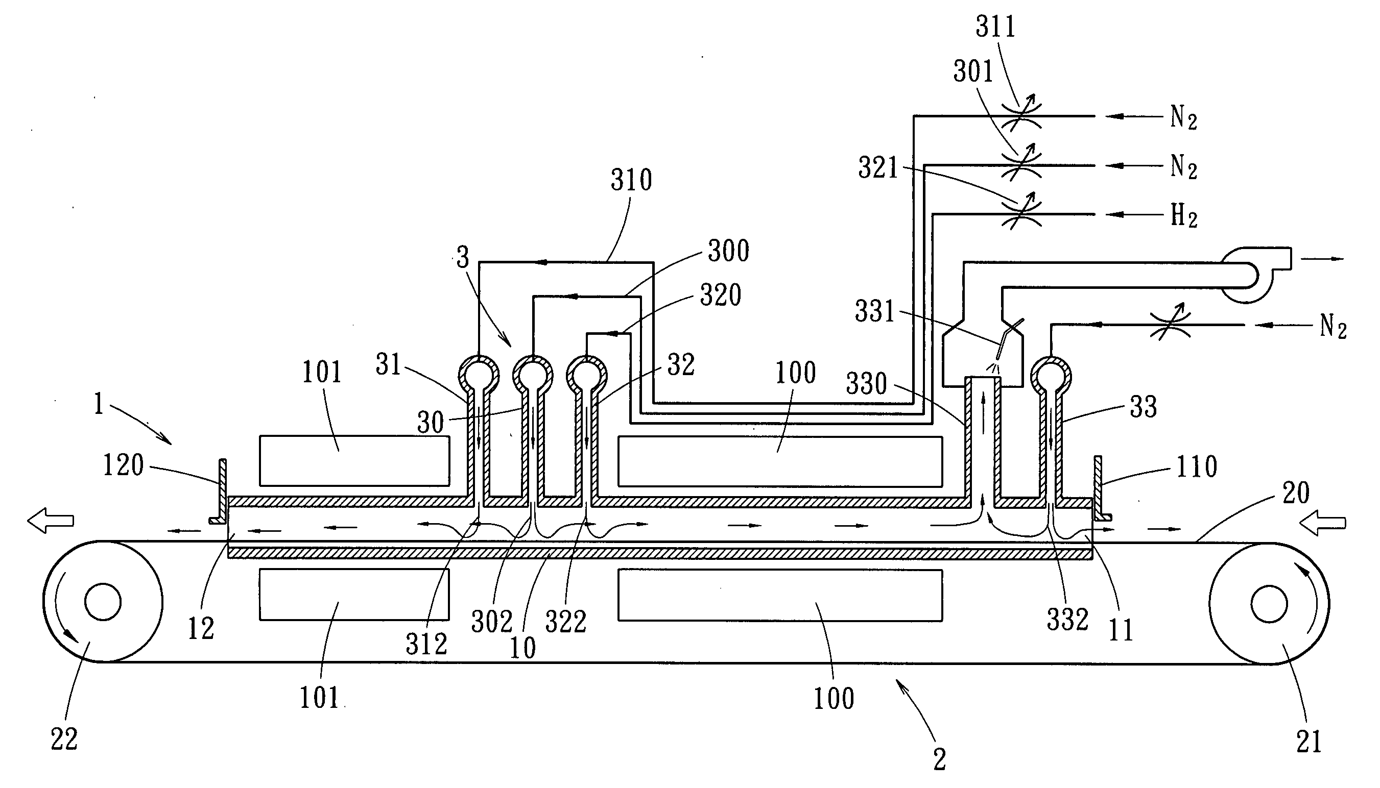
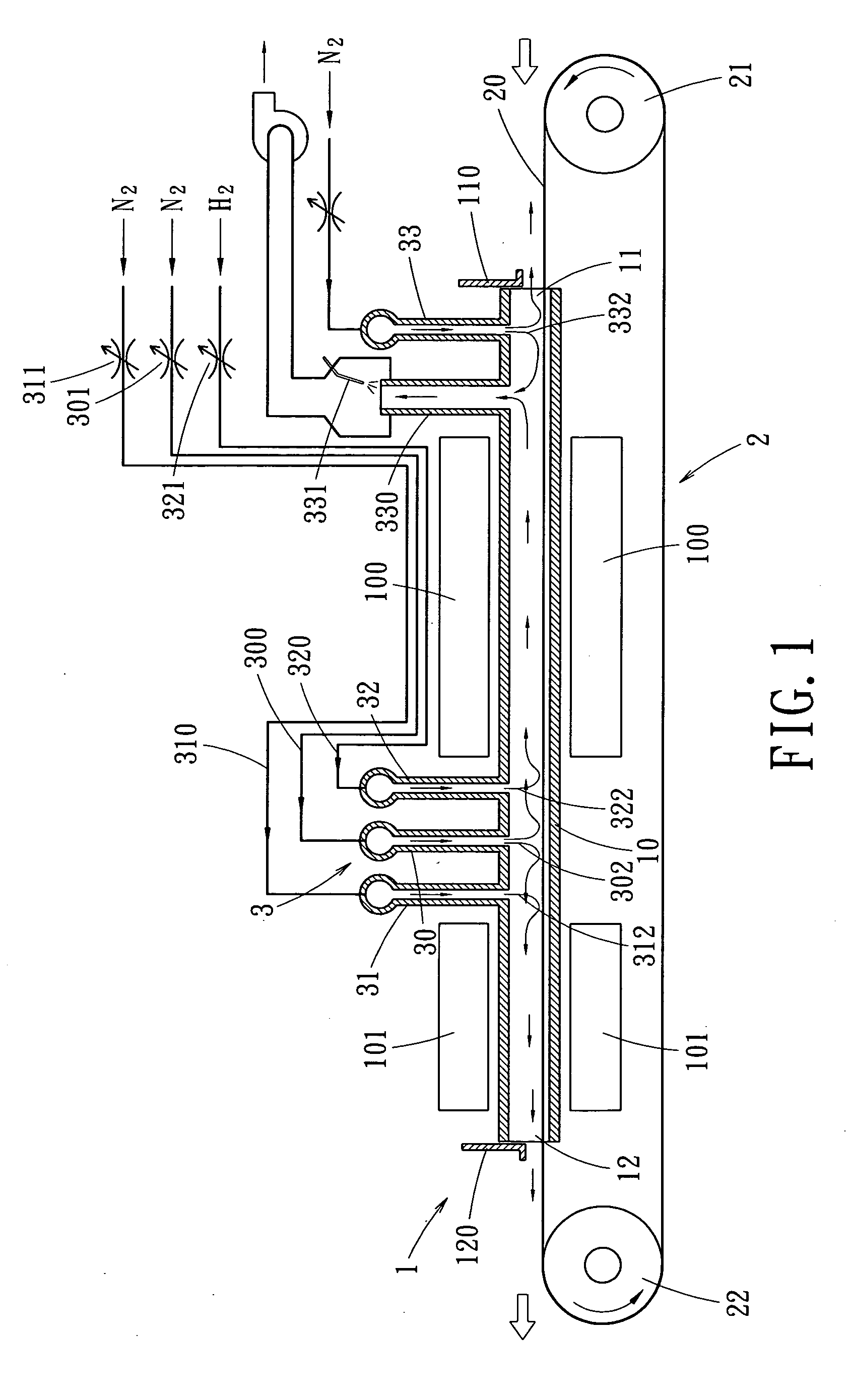
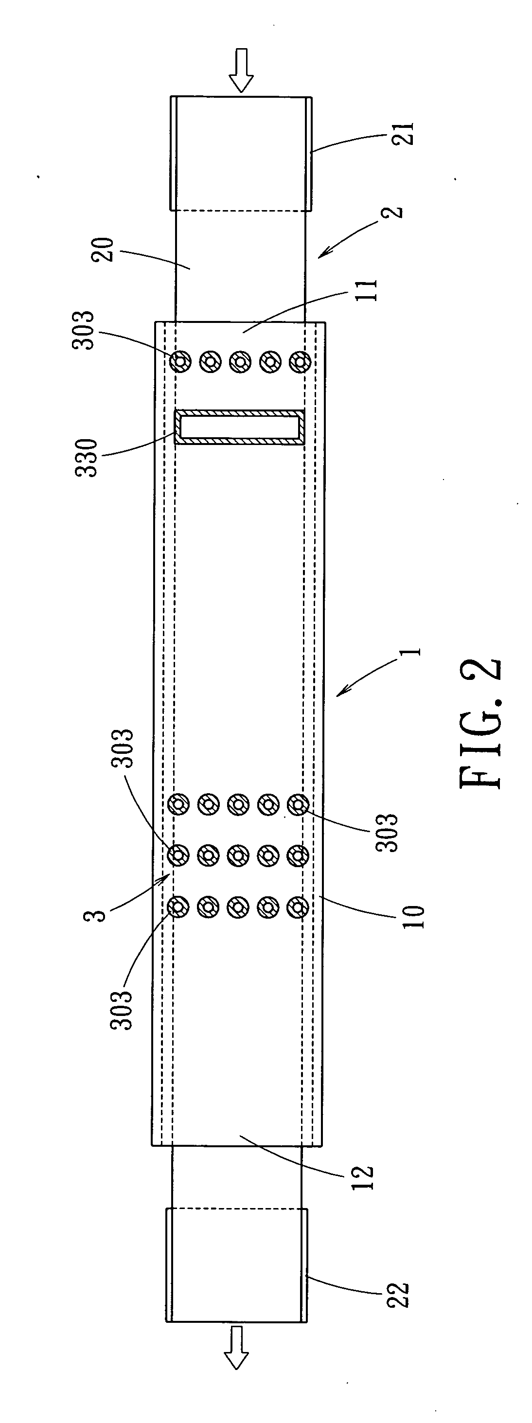
[0017]FIGS. 1 and 2 show a cross-sectional view and a top view of an annealing apparatus to perform annealing process on process materials such as heat pipes (not shown). The annealing apparatus includes a main body 1, a conveying apparatus 2 and a gas grid 3.

[0018] The main body 1 includes an elongate cylindrical hollow furnace having a gastight sidewall 10. One end of the main body 1 includes a material inlet 11 and the other end of the main body 2 includes a material outlet 12. The inlet 11 and the outlet 12 are in communication with the ambient to provide an open status of the process materials. Thereby, process materials such as heat pipes can be disposed in the annealing apparatus any time d...


PUM

PropertyMeasurementUnit
Pressureaaaaaaaaaa
Flow rateaaaaaaaaaa
Widthaaaaaaaaaa

Abstract

An annealing apparatus includes a gas tight hollow main body, a conveying apparatus and a gas grid. A heating apparatus and a cooling apparatus are installed at an inlet and an outlet of the main body, respectively. The gas grid is installed between the inlet and the outlet to blow the protecting gas into the main body, so as to form a gas screen. The conveying apparatus extends to the inlet and the outlet to convey process material such as heat pipe. Thereby, an open, non-pressure differential environment is established for performing annealing on the process material.

Description

BACKGROUND OF THE INVENTION [0001] The present invention relates in general to an annealing apparatus, and more particularly, to an annealing apparatus operative to provide an open and non-pressure differential environment for continuously perform annealing on a process material such as a heat pipe without oxidizing and affecting the luster of the process material. [0002] The conventional thermal process of a heat pipe includes a step of annealing. To avoid oxidizing the heat ppe and to provide a clean process, the annealing process is normally performed in a vacuum furnace. [0003] The conventional annealing process performed in a vacuum furnace requires a specific number of heat pipe materials disposed in a vacuum furnace. The vacuum furnace is then closed, vacuumed and heated to perform the annealing process. After the annealing process, the heat pipe materials are removed for subsequent process, and a new batch of heat pipe materials is disposed in the vacuum furnace for annealin...

Claims


Application Information

Patent Timeline
IPC IPC(8): C21D1/74C21D9/00
CPCC21D1/74C21D9/0056C21D9/0006
Inventor HSU, HUL-CHUN
Owner HSU HUL CHUN
Why Eureka
Try Eureka