Method for separating work pieces

a workpiece and workpiece technology, applied in metal sawing devices, tube shearing machines, metal sawing apparatuses, etc., can solve the problems of insufficient parallelism on cut-through workpieces without further finishing work, change in cut shape, and insufficient surface roughness, so as to reduce the development of heat, and reduce the diameter of the saw blade.

Inactive Publication Date: 2005-02-03
WEIDNER GERD JURGEN
View PDF12 Cites 9 Cited by
  • Summary
  • Abstract
  • Description
  • Claims
  • Application Information

AI Technical Summary

Benefits of technology

[0014] The saw blade moves counter to the workpiece, the development of heat being reduced.
[0015] Finishing work is no longer necessary on the workpiece, since both the saw blade and the workpiece move on a prescribed path. This has the effect that there is no change in the cut shape, i.e. the parallelism. The surface roughness is now only minimal and the saw blade runs uniformly through the workpiece.
[0016] It is also of advantage to reduce the diameter of the saw blade considerably in comparison with the diameter of the workpiece to be cut through, whereby costs and energy are saved. Moreover, the working time for sawing through the workpiece can be reduced significantly.
[0017] Since the sawing-through takes place in the case of the present invention without coolants or additives, it is of advantage that chips that are produced can be collected and melted down again without having to be passed on to a separate refining operation.
[0023] Furthermore, in the case of the apparatus it is possible to provide a catching device, which catches the cut-through workpiece and consequently prevents the saw blade from becoming jammed and damaged.

Problems solved by technology

It is disadvantageous that a change in the cut shape may occur if the workpiece consists of a hard material and it cannot easily be cut through.
Parallelism cannot be achieved on the cut-through workpiece without further finishing work.
The surface roughness is also not optimal in the case of the aforementioned methods and apparatuses, since the saws do not run uniformly through the workpiece.
To achieve good quality, it is therefore essential to carry out finishing work on the workpiece, which is undesired.
The larger the workpiece, the longer it takes to cut through the workpiece, whereby on the other hand the costs with regard to wear of the tools, energy, etc. increase.
This is time-consuming, costly and energy-intensive, which is undesired.

Method used


Image

  • Method for separating work pieces
  • Method for separating work pieces
  • Method for separating work pieces

Examples


Embodiment Construction

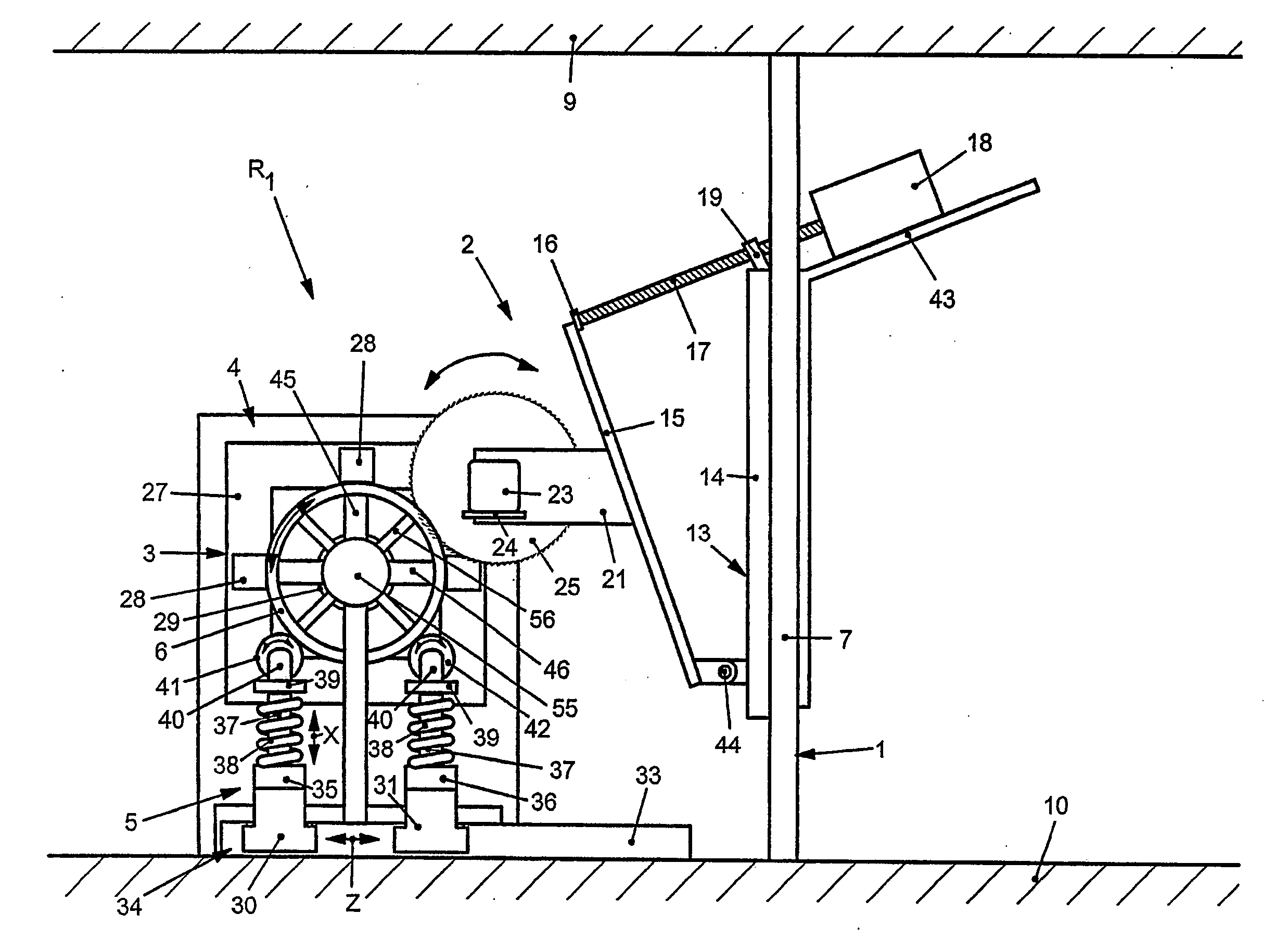
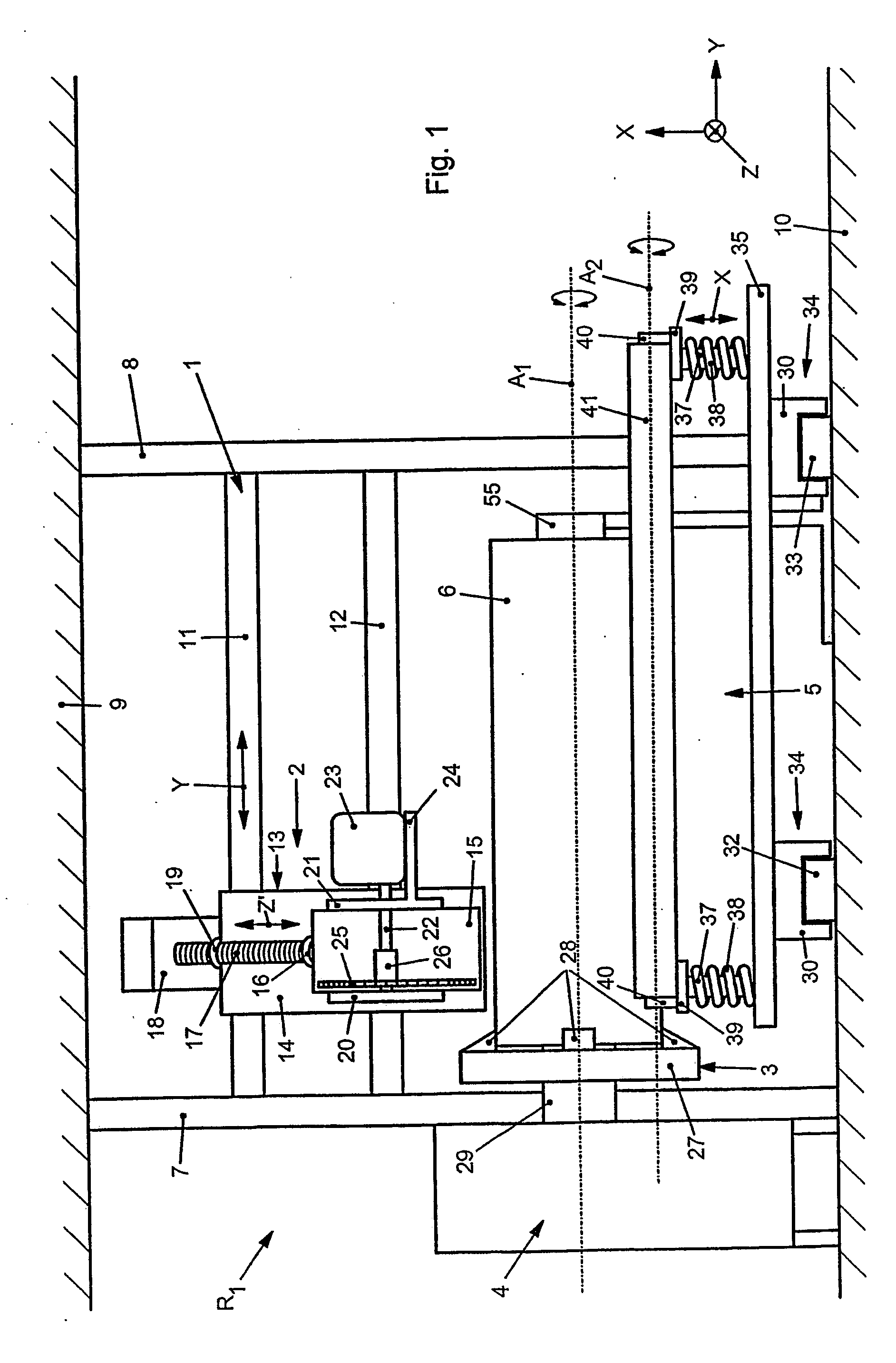
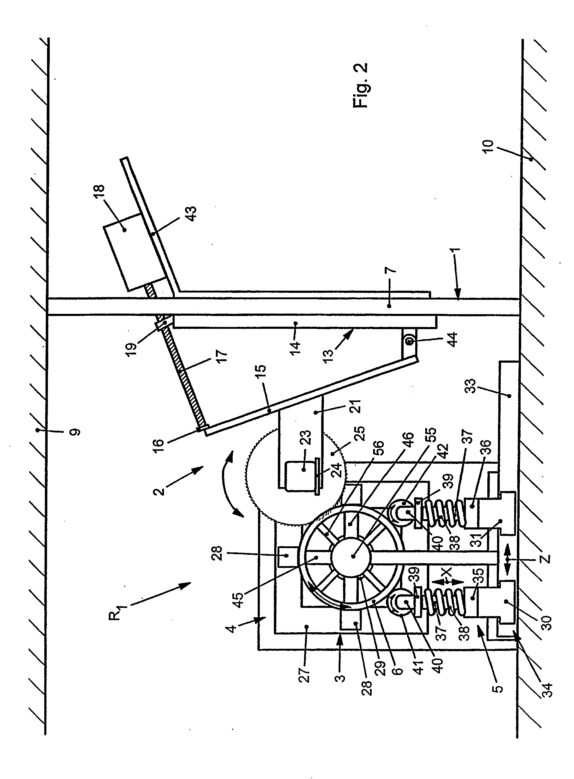
[0029] According to FIG. 1, an apparatus R1 has a machine frame 1, on which a sawing device 2 is movably arranged, and also a clamping device 3 with a driving device 4 and a receiving device 5 for a workpiece 6. Here, the workpiece 6 is a singly or multiply forged copper bush.

[0030] The machine frame 1 comprises two side supports 7, 8, which butt with their respective ends against a ceiling 9 and a base 10. Arranged between the two supports 7, 8 are at least two cross members 11, 12.

[0031] Arranged on these cross members 11 and 12 is a compound slide 13 of the sawing device 2, which has a base plate 14 and a plate 15 pivotably mounted on it. The compound slide 13 can be made to move with respect to the cross member 11, 12 in a Y direction and is also mounted in such a way that it can be fixed in a desired position.

[0032] The plate 15 has on its upper side a guide 16, into which one end of an infeeding device 17, in particular a spindle, enters. The other end of the spindle 17 is ...


PUM

PropertyMeasurementUnit
rotary movementaaaaaaaaaa
diameteraaaaaaaaaa
speedaaaaaaaaaa

Abstract

The invention relates to a method for separating workpieces, in particular forged tins, by means of at least one driving device and one clamping device, in which the work piece is maintained, whereby the work piece is cut through by means of at least one sawing device. According to the method, the workpiece may be rotatably driven in relation to the sawing device, for the separation thereof.

Description

BACKGROUND OF THE INVENTION [0001] The present invention relates to a method for separating workpieces, in particular forged bushes, with at least one driving device and one clamping device, in which the workpiece is held, the workpiece being cut through with at least one sawing device and, for cutting-through, the workpiece being driven rotatably with respect to the sawing device, and also to an apparatus for carrying out the method. [0002] Such methods and apparatuses are already known on the market in various forms and designs. Circular saws and band saws with which workpieces can be cut through are known. With these, a workpiece is clamped on the machine frame in such a way that it remains immovable during working. In the case of a circular saw, the workpiece is cut through with a rotating saw blade. In the case of a band saw, the workpiece is cut through by means of a moving endless sawing band. In both cases, the tool moves, but the workpiece does not. [0003] It is disadvantag...

Claims


Application Information

Patent Timeline
Patent Type & Authority Applications(United States)
IPC IPC(8): B23D45/12B23D21/00
CPCB23D45/126B23D45/124Y10T83/0467B23D45/12
Inventor WEIDNER, GERD-JURGEN
Owner WEIDNER GERD JURGEN
Why Eureka
Try Eureka