Light bulb puller

a puller and light bulb technology, applied in the manufacture of pliers, electrode systems, electric discharge tubes/lamps, etc., can solve the problems of difficult to release difficult to remove the lamp from its base, and the best side cutters were too clumsy

Inactive Publication Date: 2005-02-17
WESSEL RALPH
View PDF8 Cites 4 Cited by
  • Summary
  • Abstract
  • Description
  • Claims
  • Application Information

AI Technical Summary

Problems solved by technology

The difficulty occurs when it becomes necessary to replace them with a different bulb.
With the small size and tight fit it becomes difficult to release the lamp from its' base.
The side cutters were the best but were too clumsy.
Using one's fingernail often results in broken nails.

Method used


Image

  • Light bulb puller
  • Light bulb puller
  • Light bulb puller

Examples


Embodiment Construction

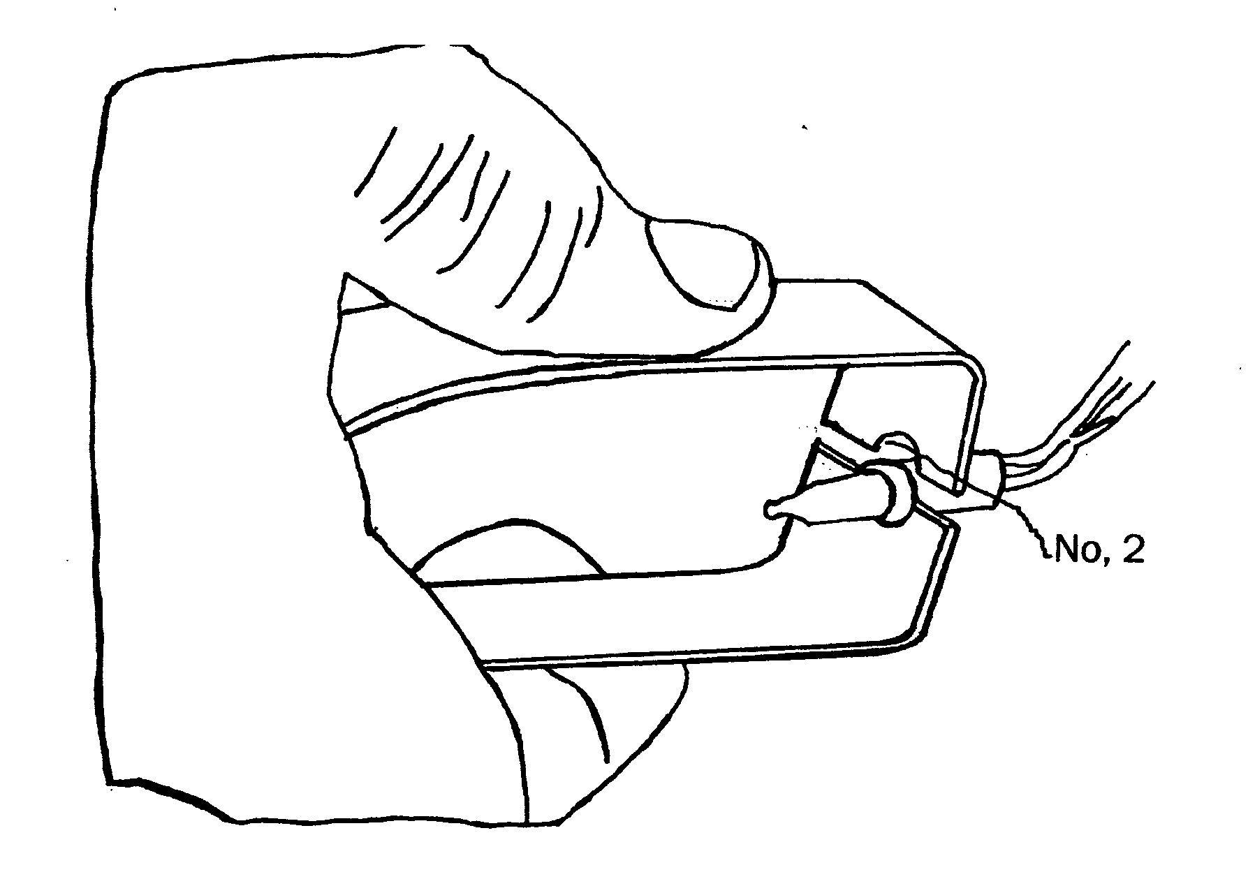
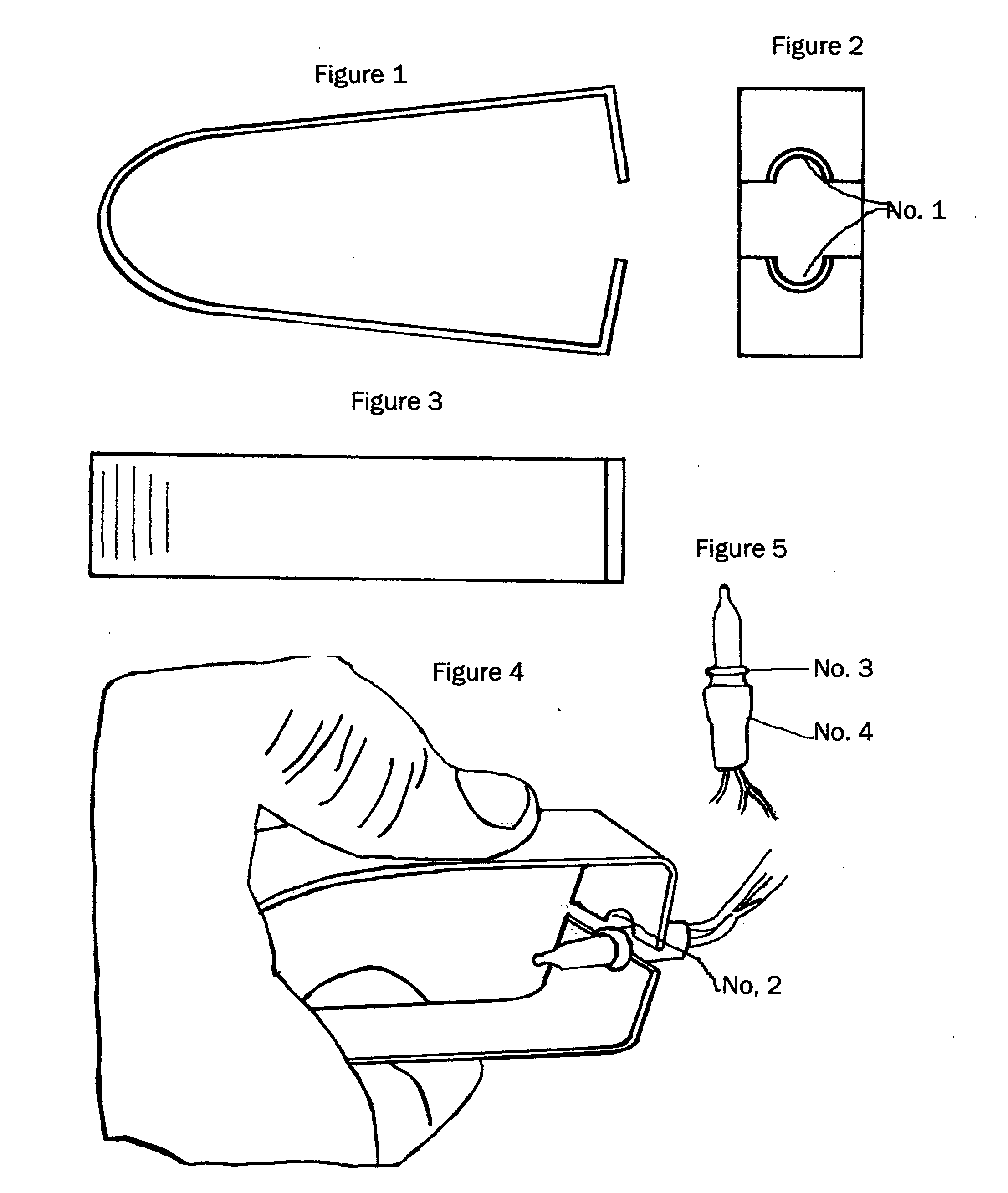
[0015] The tool consists of a flat piece of metal or a synthetic material, formed into a “U” shape with the open end of the U bent inward at 90 degrees to the side as in FIG. 1. When pressure is placed on the outside of the “U” the two ends come together. Each of the ends has a notch, as in FIG. 2, just large enough to fit around the lamp sockets in FIG. 4, No.2.

[0016] The notch can be beveled to fit in the location where the lamp bottom's shoulder FIG. 5, No.3 meets the base FIG. 5, No.4.

[0017] Side pressure on the tool compresses the tool and clamps onto the lamp base. A slight outward pull releases the lamp from its base. Releasing the side pressure on the tool allows the lamp to be released. A very simple and effective movement.

[0018] The tool should be made with just enough stiffness or spring to return to its' original shape when pressed as shown in FIG. 4 but still be easy to compress.

[0019] New

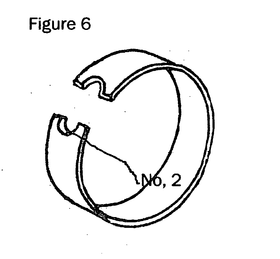
[0020] While the preferred shape is a “U” shape, it may also be in a circular...


PUM


Abstract

This is a tool to aid in the changing of small bulbs such as Christmas tree light bulbs. These bulbs are pressure fitted and there is no easy way to pull them from their sockets for repair or replacement.

Description

[0001]6561673May 13, 2003Fredrick439 / 5016167602Jan. 2, 1961Yang et al. 29 / 2786047464Mar. 11, 2000Chadbourne et al. 29 / 2745316512May 31, 1994Ell445 / 61; 29 / 764BACKGROUND [0002] This invention was developed to fill a need to have a small tool that is easy to use when removing or replacing small Christmas tree type lamp bulbs. [0003] The Christmas tree bulbs are small (overall size approximately. 1″) with a plastic bottom that fits tightly into a plastic receptacle or base. The plastic bottom of the lamp has a shoulder on top. This bottom fits into a base connected to the electric cord. [0004] The difficulty occurs when it becomes necessary to replace them with a different bulb. To insure good electrical contact it is necessary that the two plastic surfaces fit together very tightly. With the small size and tight fit it becomes difficult to release the lamp from its' base. We have tried pliers, side cutters and fingernails to pry the lamp from its' base. The side cutters were the best b...

Claims


Application Information

Patent Timeline
Patent Type & Authority Applications(United States)
IPC IPC(8): B25B9/02H01J9/00H01K3/32
CPCB25B9/02H01K3/32H01J9/003B25B27/04
Inventor WESSEL, RALPH
Owner WESSEL RALPH
Why Eureka
Try Eureka