Dual grip walking and defense baton

a baton and walking technology, applied in the field of batons, can solve the problem that the grip is not in an ideal position for use with one or the other of such devices

Inactive Publication Date: 2005-02-17
PICKENS THOMAS JR
View PDF31 Cites 26 Cited by
  • Summary
  • Abstract
  • Description
  • Claims
  • Application Information

AI Technical Summary

Problems solved by technology

In either case, the grip is not in an ideal position for use with one or the other of such devices.

Method used


Image

  • Dual grip walking and defense baton
  • Dual grip walking and defense baton
  • Dual grip walking and defense baton

Examples


Embodiment Construction

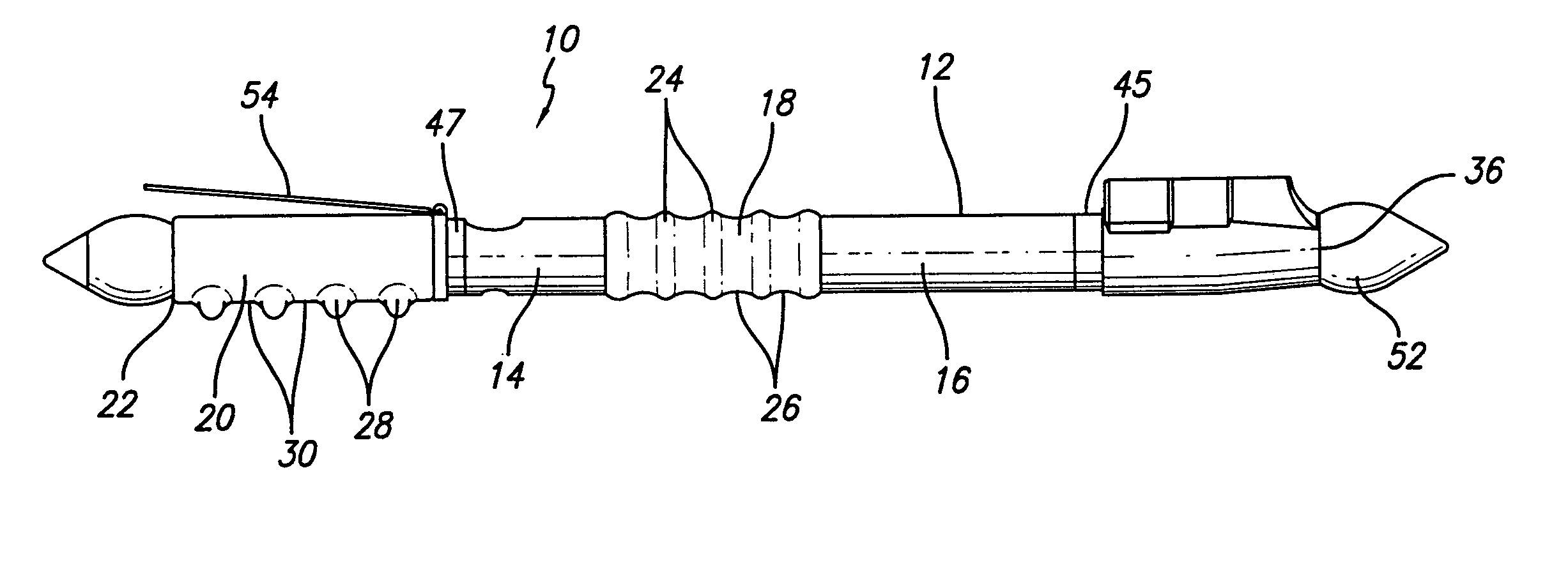
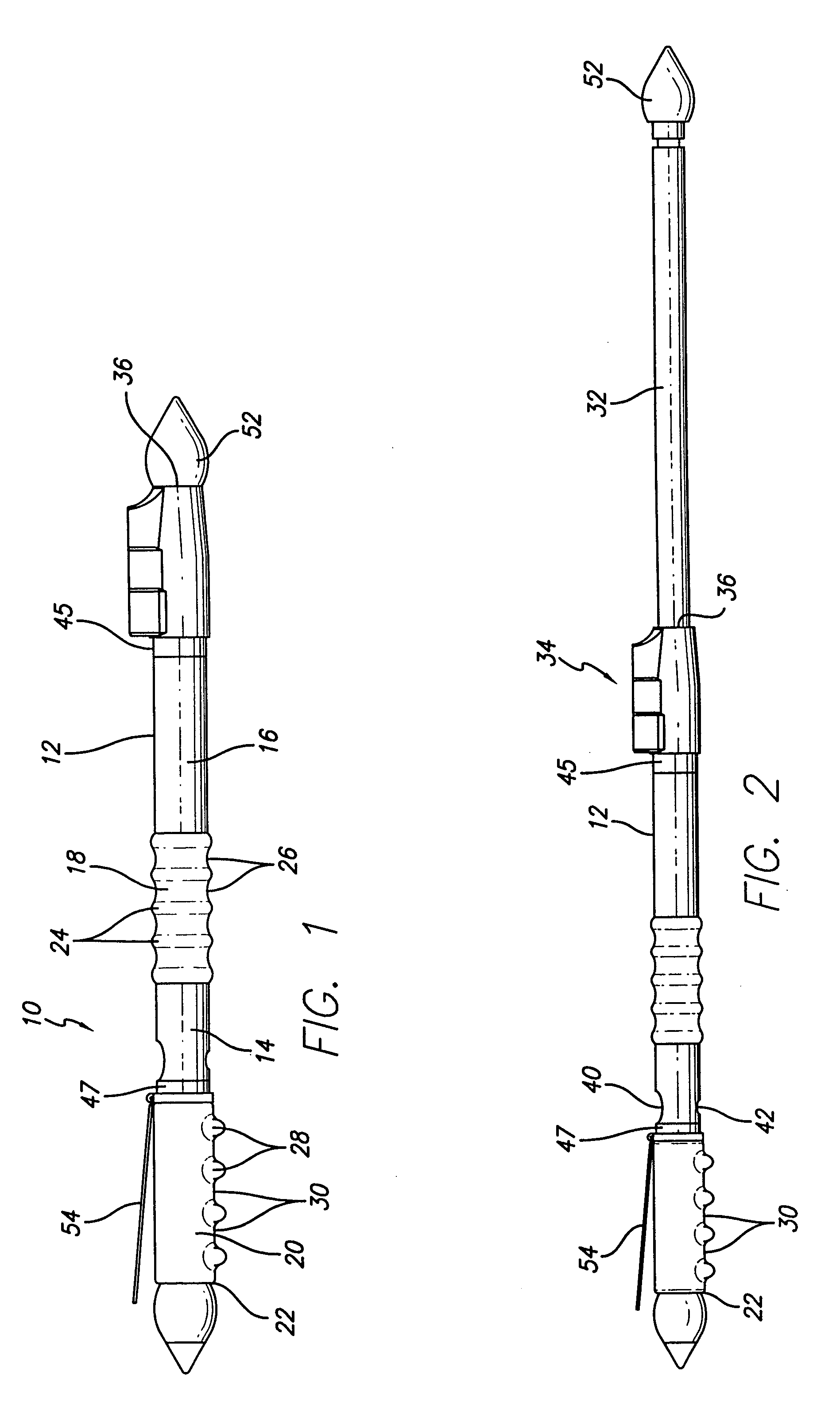
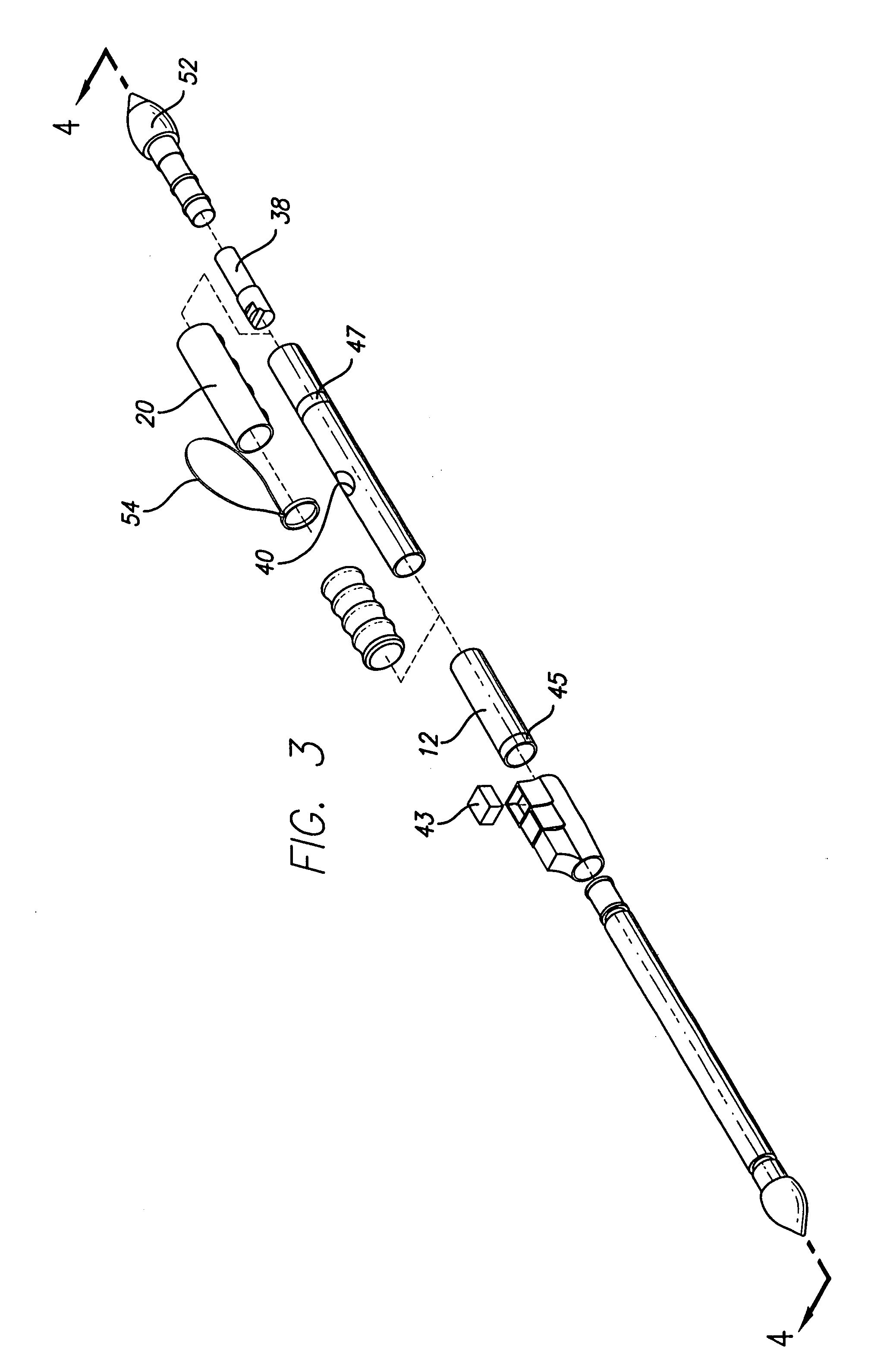
[0010] Referring to FIG. 1, a baton 10 comprises a shaft 12 formed of axially aligned cylindrical members 14 and 16 secured to opposite ends of a medial grip 18 defining a medial region of the shaft 12. An end grip 20 is located axially along a region adjacent a first end 22 of the shaft 12. The medial grip 18 is formed with a plurality of configured members 24 defining finger holds axially aligned along and around the shaft 12, which extend radially outwardly of the shaft and are sized and positioned to accommodate the fingers of a user when the baton 10 is grasped at its center. In this embodiment, there are five configured members 24 defining four finger holds 26.

[0011] The end grip 20 of the baton 10 is also formed with a plurality of configured members 28 defining finger holds 30 axially aligned along one side of the shaft, which extend outwardly of the shaft and are sized and positioned to accommodate the fingers of a user when the baton 10 is grasped by its end. In this embo...


PUM


Abstract

A dual grip walking and defense baton comprising a shaft, a medial grip located axially along a medial region of the shaft, and an end grip located axially along a region adjacent a first end of the shaft. The shaft can be telescopically extendible from a second end and can be fitted with a defense spray and / or a flashlight mechanism. A contact member can be disposed on the second shaft end for applying force to an assailant's pressure point. A wrist strap can be attached to the baton on or adjacent the end grip at a point distal from the first end of the shaft.

Description

FIELD OF THE INVENTION [0001] The invention is directed to a baton which may be carried by a person while walking and / or for self protection in the event of a threat of bodily harm. BACKGROUND OF THE INVENTION [0002] A wide variety of batons have been devised for personal protection and for use by police officers. Batons have been devised with medially located grips for balance, with contact members to apply force against an assailant, with attached or incorporated pepper spray devices, with flashlight attachments, and with looped wrist straps to facilitate carrying the baton. U.S. Pat. Nos. 4,522,398 and 5,086,377 provide batons having medially positioned grips recognizing the advantage of balanced weight distribution, the latter patent also describing the benefits of physically incorporating a flashlight mechanism and an aerosol spray device in the baton. U.S. Pat. Nos. 5,160,140, 5,370,407, 5,919,093, 6,261,188 and 6,306,040 provide batons with end grips and telescoping shafts en...

Claims


Application Information

Patent Timeline
Patent Type & Authority Applications(United States)
IPC IPC(8): A63B15/02F41B15/02
CPCA63B15/00F41B15/027A63B2207/02A63B15/02A63B2225/74
Inventor PICKENS, THOMAS JR.
Owner PICKENS THOMAS JR
Why Eureka
Try Eureka