Device for pivotally guiding variable-pitch vanes in a turbomachine

a technology of variable pitch and valve, which is applied in the direction of machines/engines, stators, liquid fuel engines, etc., can solve the problems of increasing the force that needs to be applied to the valve, the risk of the pivot seizing of the valve, and the wear of the guide bushings and the inside cylindrical surfaces of the chimney in which the bushings are mounted, so as to reduce the length of the cylindrical chimney, reduce the risk of the valve pivot seizing, and reduce the effect of temperature ris

Active Publication Date: 2005-02-24
SN DETUDE & DE CONSTR DE MOTEURS DAVIATION S N E C M A
View PDF4 Cites 2 Cited by
  • Summary
  • Abstract
  • Description
  • Claims
  • Application Information

AI Technical Summary

Benefits of technology

[0008] A corresponding advantage of the invention is that the device makes it possible to reduce the length of the cylindrical chimneys which are formed on the casing, thus making the casing easier to manufacture and machine.
[0009] Another corresponding advantage of the invention is that the means for guiding the vane pivots outside the casing are further removed from the source of heat formed by the flow of gas in the turbomachine and are thus subjected to a smaller temperature rise.
[0010] Consequently, these guide means can be made out of less expensive materials having a low coefficient of friction.
[0011] In addition, in the invention, the ring for controlling these vanes is supported and centered around the casing by means of the pivot portions of the vanes which extend outside the casing, thus avoiding any need to center and support said ring directly on the casing of the turbomachine.
[0012] In addition, the control ring is at substantially the same temperature as the above-mentioned stationary element so their thermal expansions are of the same order of magnitude, which improves guidance of the control ring. This results in a reduction in the force required to drive the variable-pitch vanes, thus making it possible to use means that are simpler and less expensive for driving these vanes.
[0013] According to another characteristic of the invention, the above-mentioned stationary element includes means for pivotally guiding the pivots of a plurality of vanes forming part of the same row of variable-pitch vanes.

Problems solved by technology

The axial chimneys of the casing are relatively short in length, such that the vanes, which are subjected to the forces exerted by the flow of gas, tend to tilt obliquely relative to their pivot axes, thereby leading to wear in the guide bushings and in the inside cylindrical surfaces of the chimneys in which the bushings are mounted.
This leads to a risk of the vane pivots seizing and to an increase in the force that needs to be applied to the vanes in order to make them pivot about their pivot axes.
This also leads to a risk of the radially-inner ends of the vanes coming into contact with the rotor of the turbomachine, and to corresponding risks of damage, destruction, and fire because of the intense heating that arises by the ends of the vanes rubbing against the rotor.

Method used


Image

  • Device for pivotally guiding variable-pitch vanes in a turbomachine
  • Device for pivotally guiding variable-pitch vanes in a turbomachine
  • Device for pivotally guiding variable-pitch vanes in a turbomachine

Examples


Embodiment Construction

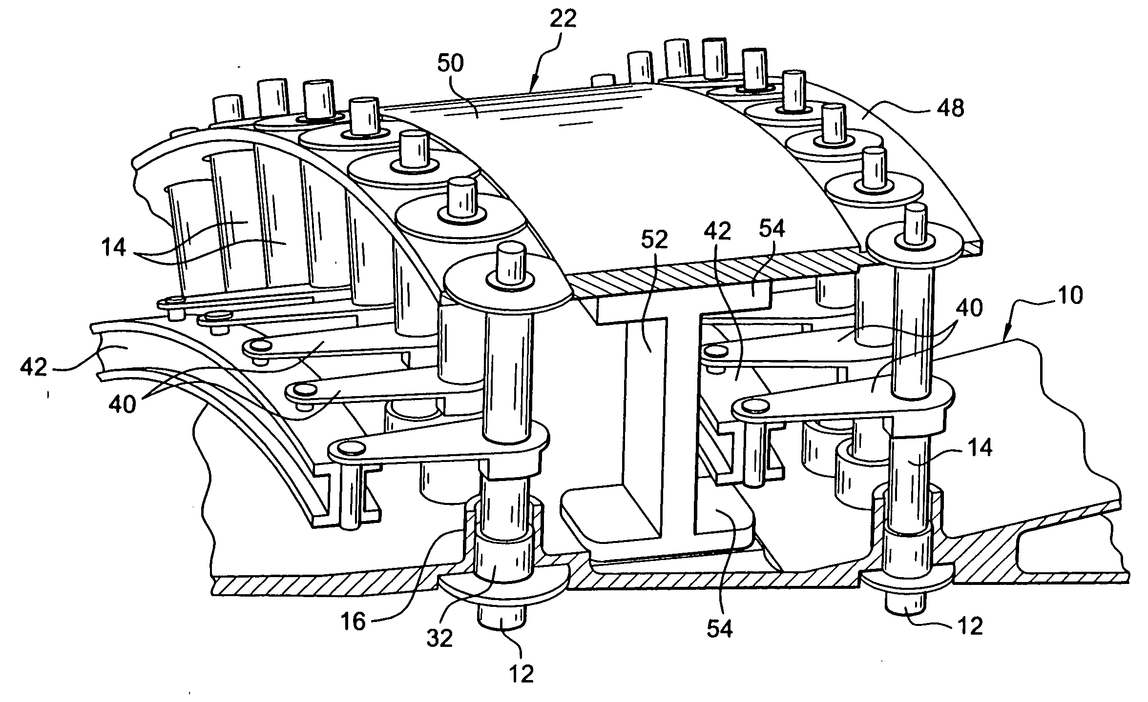
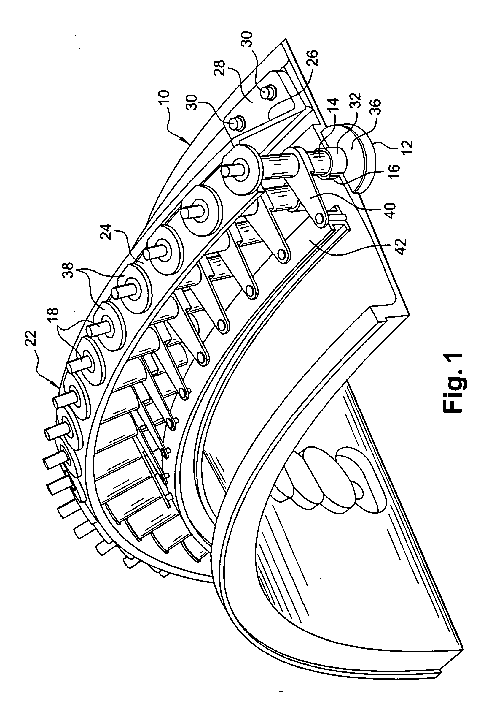
[0023] In FIGS. 1 and 2 which show a first embodiment of the invention, reference 10 designates a turbomachine casing that is generally cylindrical in shape and that is centered on the axis of rotation of a rotor of the turbomachine.

[0024] The turbomachine comprises one or more stator stages formed by gas flow guide vanes 12, these vanes being mounted on the casing 10 to pivot about axes that are radial relative to the axis of rotation of the rotor, and only the radially-outer portions thereof or “vane roots” being shown in the drawings.

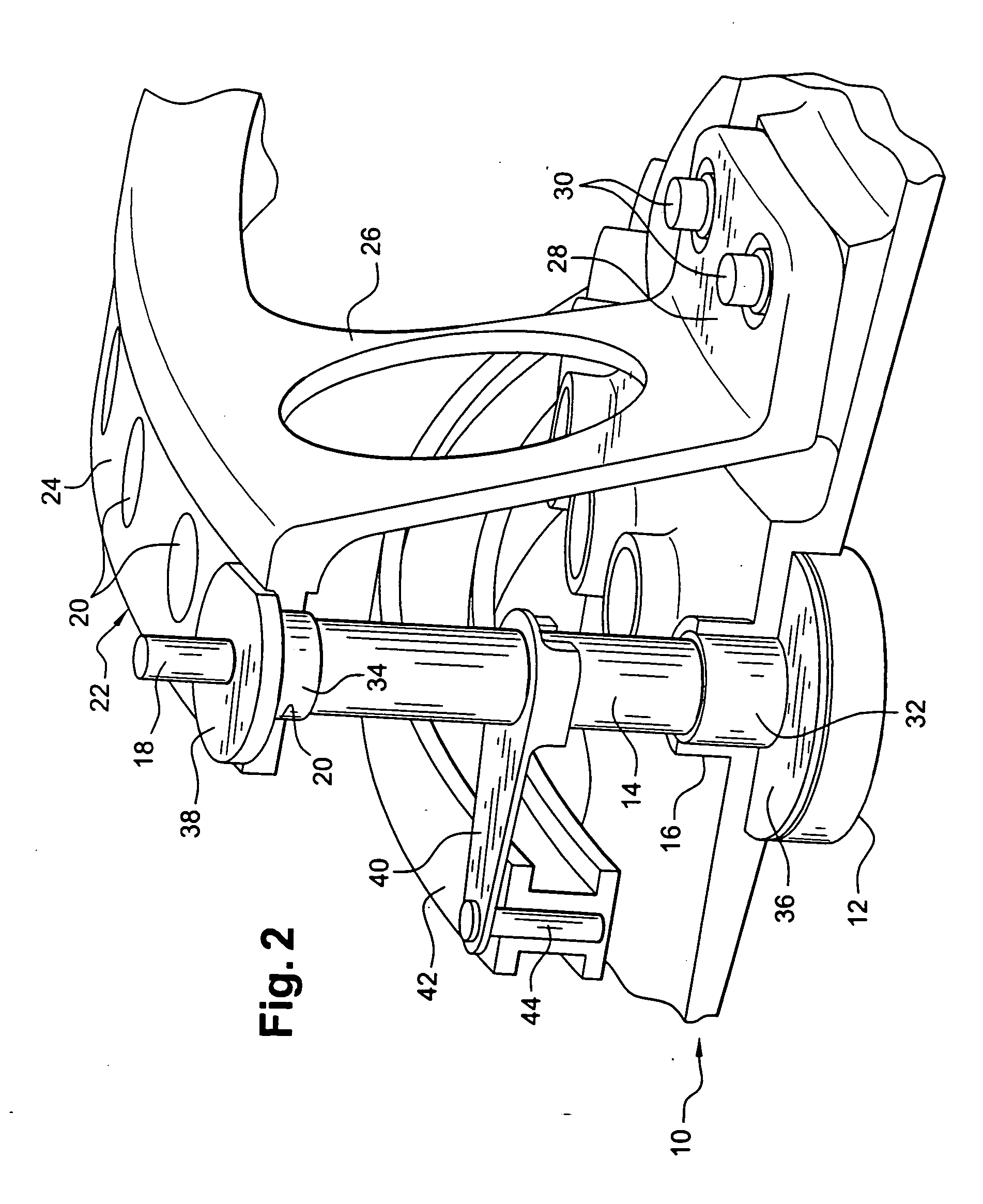
[0025] Each vane 12 includes a cylindrical axial shank 14 extending inside a radial cylindrical chimney 16 of the casing 10 and having a radially-outer end portion 18 extending beyond the chimney 16 and which is pivotally guided in a cylindrical orifice 20 of a stationary element 22 which surrounds the casing 10 on the outside and at a distance therefrom.

[0026] In the embodiment shown, the stationary element 22 comprises a cylindrical wall 24 cent...


PUM


Abstract

A device for guiding pivoting of variable-pitch vanes in a turbomachine, each vane having a pivot formed by a cylindrical axial shank which is guided in a cylindrical chimney of the casing and in a cylindrical orifice of a stationary element which surrounds the outside of the casing and which is centered and fixed relative thereto. The invention improves pivotal guidance of variable-pitch vanes.

Description

[0001] The invention relates to a device for pivotally guiding variable-pitch vanes in a turbomachine such as an aviation turbojet or turboprop. BACKGROUND OF THE INVENTION [0002] In known guide devices, each vane has one end pivotally mounted on the casing of the turbomachine about a respective axe that is radial relative to the axis of rotation of the rotor, and for this purpose the vanes have respective axial cylindrical shanks forming pivots that are pivotally guided in bearings mounted in radial cylindrical chimneys of the turbomachine casing. These bearings are generally made of bushings of material having a low coefficient of friction, such as sintered bronze, for example. [0003] The axial chimneys of the casing are relatively short in length, such that the vanes, which are subjected to the forces exerted by the flow of gas, tend to tilt obliquely relative to their pivot axes, thereby leading to wear in the guide bushings and in the inside cylindrical surfaces of the chimneys...

Claims


Application Information

Patent Timeline
Patent Type & Authority Applications(United States)
IPC IPC(8): F01D17/16F01D9/02F04D29/56
CPCF01D17/162
Inventor DEBENEIX, PIERRELANGLOIS, ARNAUDBOSTON, ERICKLEMAN, FREDERICGARNIER, VINCENTAUDET, JACQUES
Owner SN DETUDE & DE CONSTR DE MOTEURS DAVIATION S N E C M A
Why Eureka
Try Eureka