DC-DC converter

Active Publication Date: 2005-03-17
FUJI ELECTRIC CO LTD
View PDF3 Cites 106 Cited by
  • Summary
  • Abstract
  • Description
  • Claims
  • Application Information

AI Technical Summary

Benefits of technology

is to provide a DC-DC converter in which high efficiency in a wide load range is maintained an

Problems solved by technology

In this case, when a load current becomes below 20 to 30% of a rated current, the switch device converts the voltage through the switching with extremely low efficiency.
As

Method used


Image

  • DC-DC converter
  • DC-DC converter
  • DC-DC converter

Examples


first embodiment

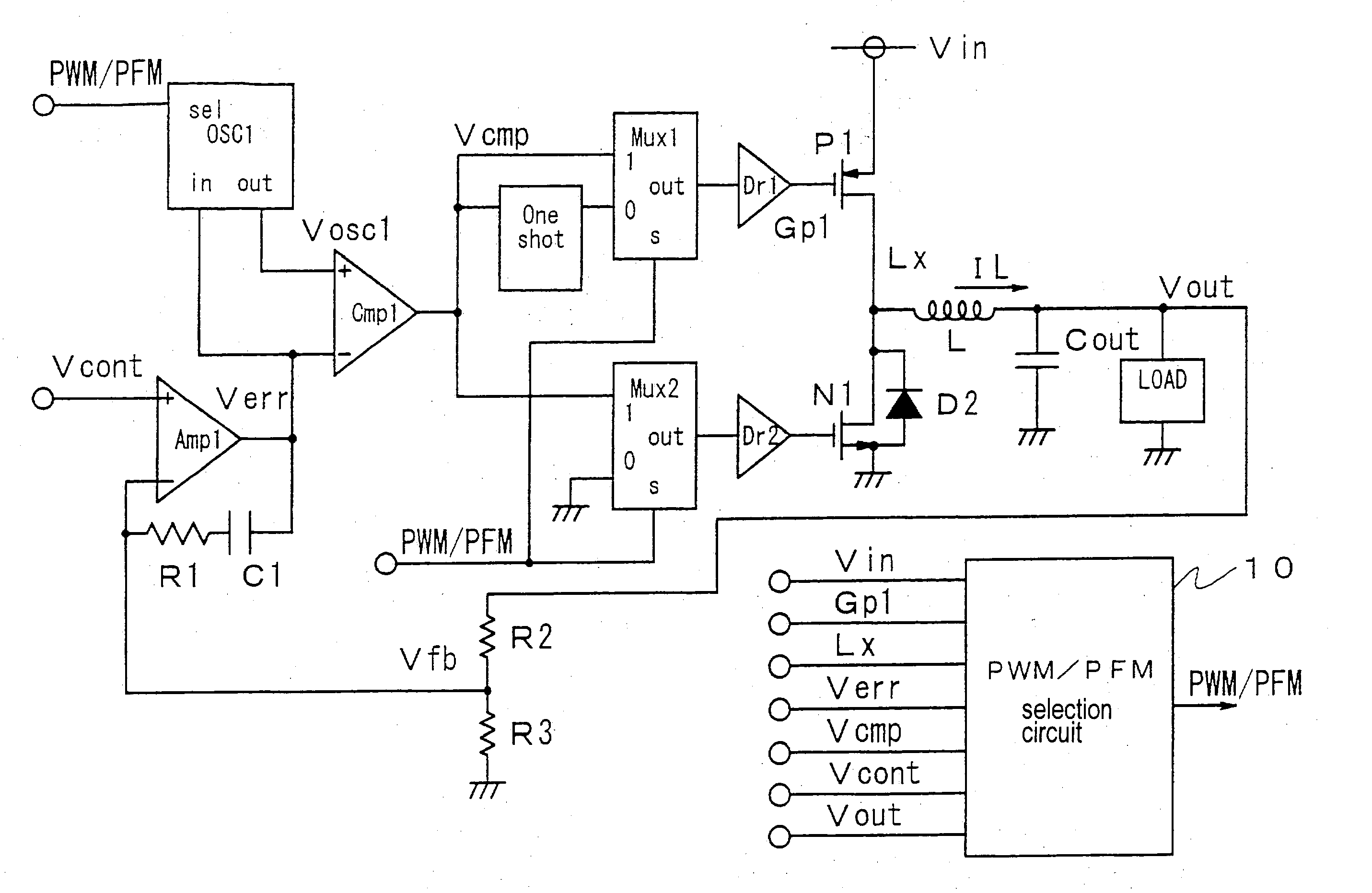
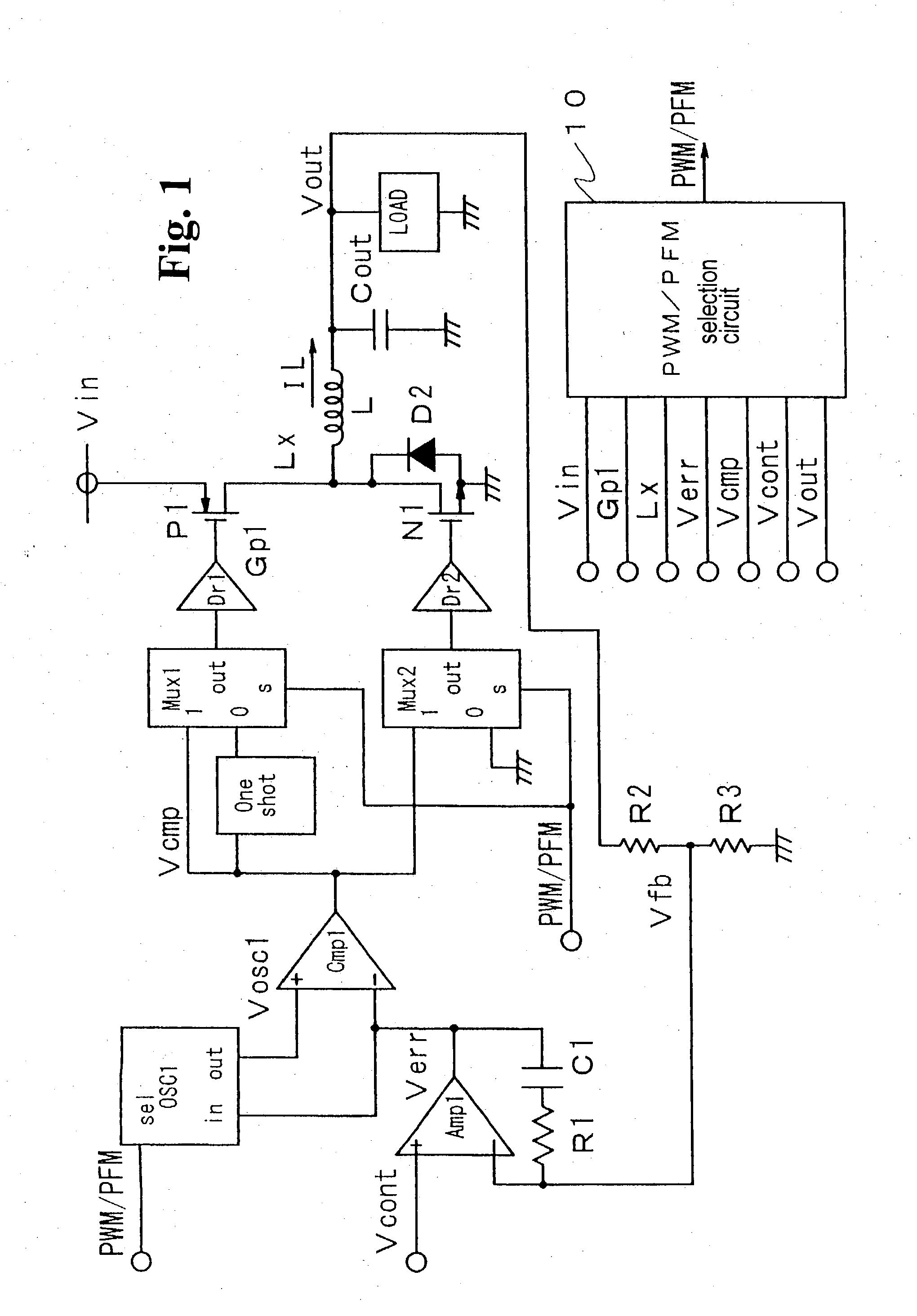
Hereunder, embodiments of the invention will be described in detail with reference to the accompanying drawings. FIG. 1 is a block circuit diagram of a DC-DC converter according to the invention. The DC-DC converter converts an input power supply voltage Vin to a certain voltage level and supplies the converted voltage to a load LAOD.

The DC-DC according includes an error amplifier (operational amplifier) Amp1, a capacitor C1 for phase compensation, a resistance R1 for phase compensation, a feedback resistance R2, a feedback resistance R3, an oscillator circuit OSC1, a comparator Cmp1 for pulse width modulation, a one-shot circuit one-shot, multi-plexer circuits Mux1 and Mux2, driver circuits Dr1 and Dr2, a p-channel transistor (MOSFET) P1 for outputting, an n-channel transistor (MOSFET) N1 for outputting, a choke coil L, a diode D2, a smoothing capacitor Cout, and a PWM / PFM selection circuit 10.

The PWM / PFM selection circuit 10 receives the input power supply voltage Vin, a gate s...


PUM


Abstract

A DC-DC converter switches a semiconductor switch device for converting a DC voltage to a certain level and supplies the converted DC voltage to a load. The DC-DC converter is configured to be able to switch between a first feedback control mode and a second feedback control mode. The DC-DC converter selects the second feedback control mode when a load current flowing through the load is below a predetermined value. The DC-DC converter selects the first feedback control mode when a level of the DC voltage supplied to the load changes irrespective of a value of the load current.

Description

BACKGROUND OF THE INVENTION AND RELATED ART STATEMENT The invention relates to a DC-DC converter for switching a semiconductor switch device to convert a DC voltage to a certain level and for supplying the DC voltage to a load. Specifically, the invention relates to a DC-DC converter that reduces a switching loss of the semiconductor switch device even when an output voltage fluctuates. A DC-DC converter switches a semiconductor switch device to convert a DC voltage, and conducts feedback control to maintain an output voltage supplied to a load at a certain value. In this case, when a load current becomes below 20 to 30% of a rated current, the switch device converts the voltage through the switching with extremely low efficiency. In order to prevent the voltage conversion efficiency from lowering at a low load current, in a known method, a switching frequency is lowered according to the decease in the load current to reduce a loss associated with the switching of the switch devic...

Claims


Application Information

Patent Timeline
IPC IPC(8): H02M3/156H02M3/155
CPCH02M3/156H02M3/155
Inventor YOSHIDA, YUTAKA
Owner FUJI ELECTRIC CO LTD
Why Eureka
Try Eureka