Liquid crystal display and driving method thereof

a technology of liquid crystal display and driving method, which is applied in the direction of instruments, static indicating devices, etc., can solve the problems of degrading efficiency and quality of liquid crystal display, insufficient charging time of pixel, and more rapid charging of pixel, so as to reduce the voltage swing of pixel and rapid charging pixels

Active Publication Date: 2005-03-17
AU OPTRONICS CORP
View PDF3 Cites 15 Cited by
  • Summary
  • Abstract
  • Description
  • Claims
  • Application Information

AI Technical Summary

Benefits of technology

[0009] Accordingly, an object of the present invention is to provide a driving method for rapidly charging pixels of a liquid crystal display by reducing the voltage swing of a pixel during charging period.

Problems solved by technology

However, as resolution of the liquid crystal display increases, charge time of the capacitors Clc10 and Cst10 decreases so that the pixel voltage Vpx10 cannot reach the voltage level corresponding to the image, degrading efficiency and quality of the liquid crystal display.
Trends toward high resolution LCD devices and short charge time of pixels result in the problem of insufficient charging time of the pixel, such that there is a need to reduce the amplitude of pixel voltage swing during charging period, thereby more rapidly charging the pixel.

Method used


Image

  • Liquid crystal display and driving method thereof
  • Liquid crystal display and driving method thereof
  • Liquid crystal display and driving method thereof

Examples


Embodiment Construction

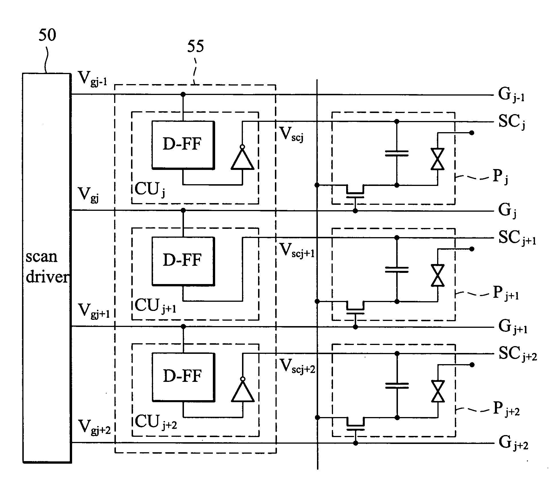
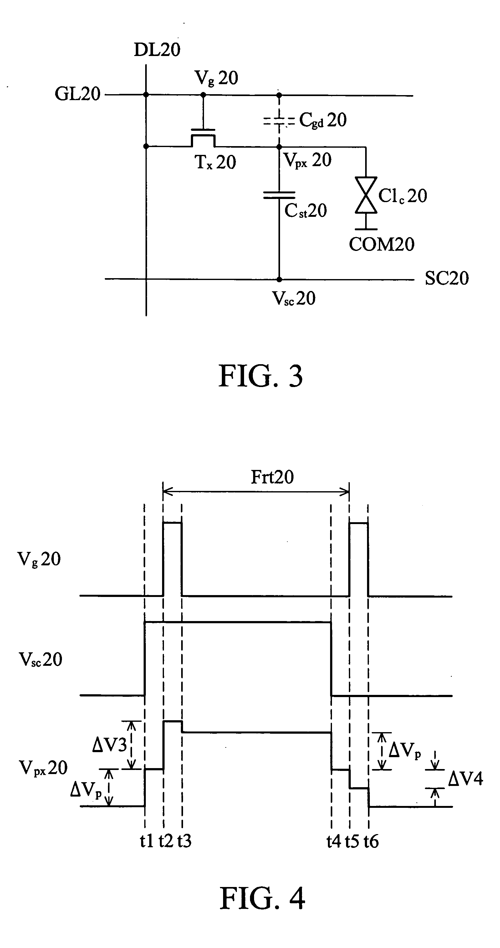
[0022]FIG. 3 is a unit circuit diagram of a liquid crystal display of the present invention. A liquid crystal display unit comprises a storage electrode SC20, a common electrode COM20, a data line DL20, a scan line GL20, a thin film transistor (hereinafter referred to as “TFT”) Tx20, a storage capacitor Cst20, and a liquid crystal cell Clc20. The data line DL20 is coupled to a first terminal of the TFT Tx20, and the scan line GL20 is coupled to a gate of the TFT Tx20. The storage capacitor Cst20 is coupled between a second terminal of the TFT Tx20 and the storage electrode SC20. The liquid crystal cell Clc20 is coupled between a second terminal of the TFT Tx20 and the common electrode COM20. In addition, a capacitor Cgd20 is a parasitic capacitor.

[0023] The driving method of the present invention is described below.

[0024] Referring to FIG. 4, at time t1, a pre-charging signal Vsc20 applied to the storage electrode SC20 changes from a low-level voltage to a high-level voltage. Sinc...


PUM


Abstract

A driving method of liquid crystal display. Voltage levels of pre-charging signals applied to storage electrodes vary before scan signals are applied to scan lines. Partial response voltage of the variations in voltage levels of pre-charging signals are respectively coupled to storage capacitors within pixels by capacitors. When the scan signals are applied to the scan lines, voltage swings of the pixel capacitors charged by image data on data lines decrease, rapidly charging the pixels.

Description

BACKGROUND OF THE INVENTION [0001] 1. Field of the Invention [0002] The present invention relates to a liquid crystal display and driving method thereof, and in particular to a liquid crystal display and driving method thereof for rapidly charging pixel in the liquid crystal display. [0003] 2. Description of the Related Art [0004]FIG. 1 is a unit circuit diagram of a conventional liquid crystal display. As shown in FIG. 1, the liquid crystal display comprises a common electrode COM10, a data line DL10, a scan line GL10, a thin film transistor (hereinafter referred to as “TFT”) Tx10, a storage capacitor Cst10, and a liquid crystal cell Clc10. The data line DL10 is coupled to a first terminal of the TFT Tx10, the scan line GL10 is coupled to a gate of the TFT Tx10, and the storage capacitor Cst10 is coupled between a second terminal of the TFT Tx10 and the common electrode COM10. In addition, a capacitor Cgd10 is a parasitic capacitor. [0005] According to FIG. 1, in the conventional l...

Claims


Application Information

Patent Timeline
Patent Type & Authority Applications(United States)
IPC IPC(8): G09G3/36
CPCG09G3/3655G09G2310/0251G09G2300/0876G09G3/3677
Inventor YU, JIAN-SHEN
Owner AU OPTRONICS CORP
Why Eureka
Try Eureka