Infrared detection sensor

a detection sensor and infrared technology, applied in the field of infrared detection sensors, can solve problems such as inability to detect objects, and detection errors

Inactive Publication Date: 2005-03-31
OPTEX CO LTD
View PDF1 Cites 3 Cited by
  • Summary
  • Abstract
  • Description
  • Claims
  • Application Information

AI Technical Summary

Benefits of technology

[0015] In order to achieve the above objects, an infrared detection sensor according to the present invention is provided with a phototransmitter including a plurality of light projection portions projecting independent infrared rays, and a photoreceiver including a plurality of light reception portions which are respectively placed opposite to the plurality of light projection portions, wherein different infrared rays are projected from the plurality of light projection portions to the plurality of opposite light reception respectively, at different timings and with predetermined intervals, forming a plurality of independent detection zones; an intrusion of an object into the detection zones is detected when an object intruding into the detection zones disrupts the projection of the infrared rays from the phototransmitter to the photoreceiver; and the phototransmitter is provided with a light projection control means for increasing a signal output level of a leading edge portion of the infrared rays.

Problems solved by technology

Still, since the light reception portions receive mixed signal data from the upper and lower light projection portions, detection errors happen unless the signal data in the upper and lower infrared rays are identical.
However, if the signal data of the infrared rays projected from the upper and lower light projection portions are signal data representing identical information, they cannot detect objects that disrupt only one of the infrared rays, for example, they cannot detect small animals which disrupt the infrared rays projected from the lower light projection portion only.
As a result, with the sensitivity to infrared rays of the infrared detection sensor according to JP H9-297184A, the input level of the received infrared rays is lower in the infrared detection sensors which project the infrared rays from upper and lower light projection portions simultaneously, so that the detection operation for detecting an object intruding into the detection zone becomes unstable, and the light projection distance cannot be prolonged because detection errors are likely to happen.

Method used


Image

  • Infrared detection sensor
  • Infrared detection sensor
  • Infrared detection sensor

Examples


Embodiment Construction

[0031] Hereinafter, an embodiment of the invention is described with reference to the appended drawings. The following description relates to the case of applying the invention to an infrared detection sensor for crime prevention. Infrared detection sensors according to the invention, however, are not limited to this, and can be used in various applications.

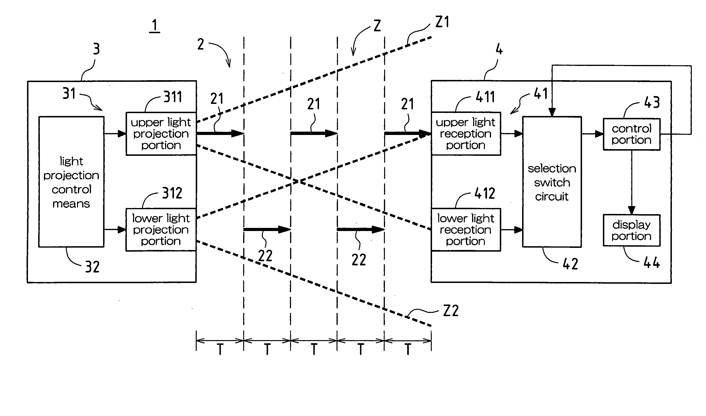
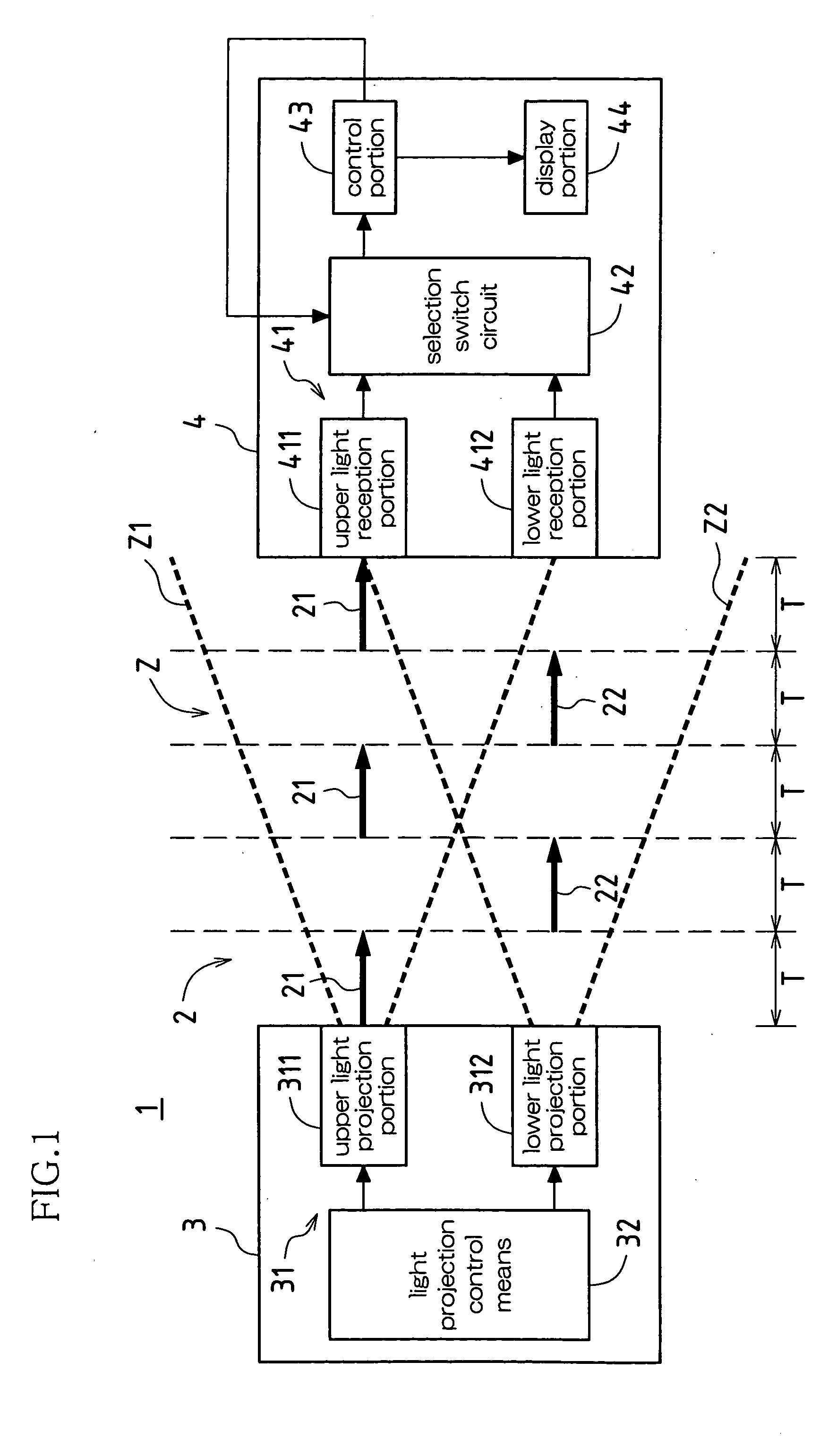
[0032] As shown in FIG. 1, an infrared detection sensor 1 according to this embodiment is provided with a phototransmitter 3 including a light projection portion 31 projecting infrared rays 2, and a photoreceiver 4 including a light reception portion 41 receiving the infrared rays 2 from the light projection portion 31. An intrusion of an object into a detection zone Z is detected when a projection of the infrared rays 2 from the phototransmitter 3 to the photoreceiver 4 is disrupted.

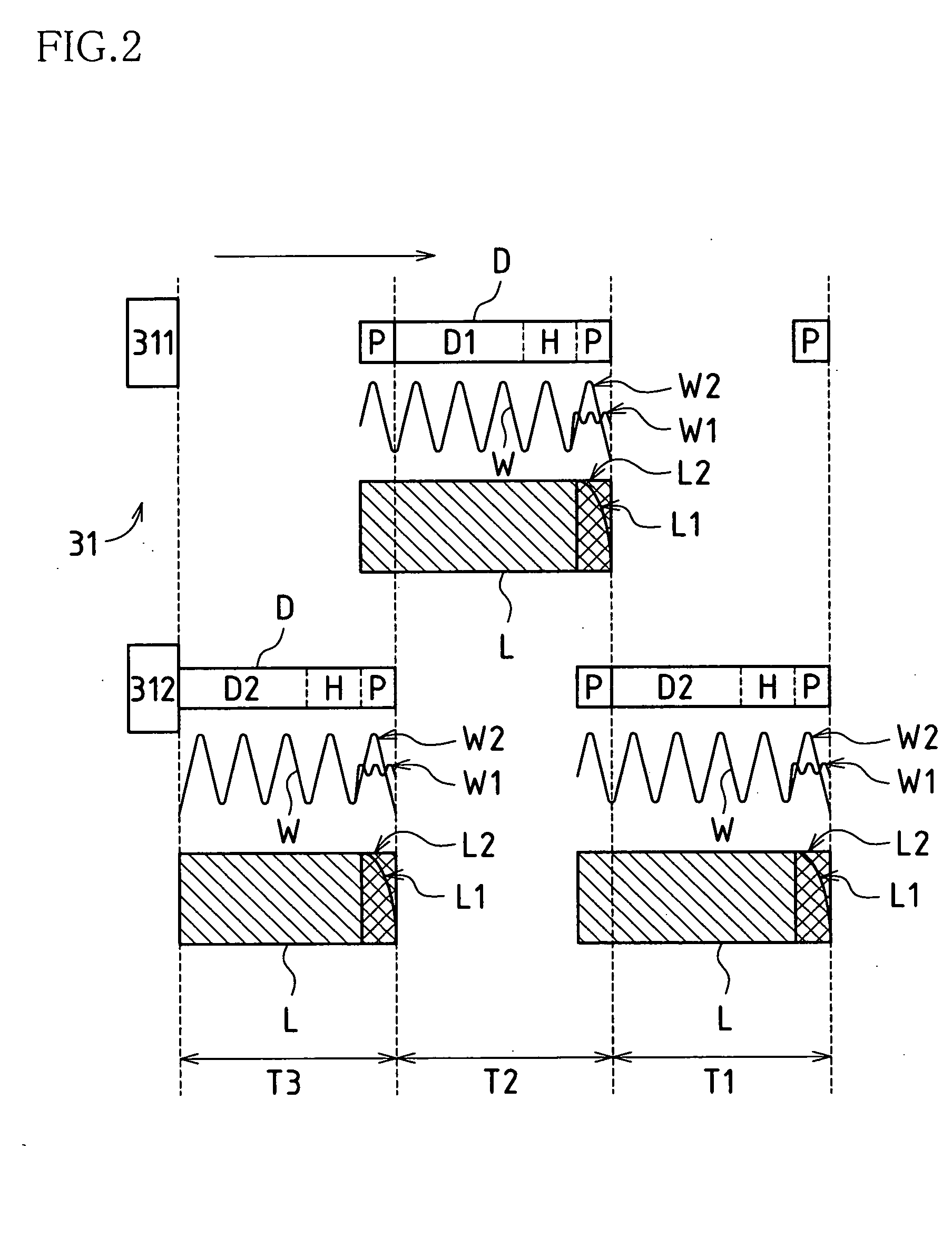
[0033] The light projection portion 31 is made of upper and lower light projection portions (an upper light projection portion 311 and a lower lig...


PUM


Abstract

An infrared detection sensor is provided with a phototransmitter including light projection portions projecting infrared rays, and a photoreceiver including light reception portions, which are respectively placed opposite to the light projection portions, receiving the infrared rays from the light projection portions. The light projection portions are made of upper and lower light projection portions, and the light reception portions are made of upper and lower light reception portions. The phototransmitter includes a light projection control means for increasing a signal output level of a leading edge portion in the infrared rays projected from the light projection portions.

Description

CROSS-REFERENCE TO RELATED APPLICATION [0001] The present application claims the priority under 35 U.S.C. §119(a) on Patent Application Number 2003-333722, filed in Japan on Sep. 25, 2003, the subject matter of which is hereby incorporated herein by reference.BACKGROUND OF THE INVENTION [0002] 1. Field of the Invention [0003] The present invention relates to infrared detection sensors. In particular, the present invention relates to infrared detection sensors which detect an intrusion of an object into a detection zone when an object intruding into the detection zone disrupts infrared rays projected from light projection portions to light reception portions. [0004] 2. Description of the Related Art [0005] Among sensors using infrared rays, there are infrared detection sensors, which are provided with light projection portions and light reception portions, and which detect a status of disruption of infrared rays projected from the light projection portions. [0006] Among such conventi...

Claims


Application Information

Patent Timeline
Patent Type & Authority Applications(United States)
IPC IPC(8): G01J1/42G01V8/12G01V8/20G08B13/183H03K17/78
CPCG08B13/183G01V8/20G01J1/42G01V8/12
Inventor IWASAWA, MASASHI
Owner OPTEX CO LTD
Why Eureka
Try Eureka