Image display device

a technology of image display and display panel, which is applied in the field of image display device, can solve the problems of adverse influence on the inability to increase the illumination quantity of light from the lamp housing in the lower frame to the image display panel, and the inability to increase the illumination quantity of the lamp housing in the lower frame, so as to ensure mechanical strength, enhance the optical efficiency of the lamp, and eliminate drawbacks

Active Publication Date: 2005-04-07
PANASONIC LIQUID CRYSTAL DISPLAY CO LTD +1
View PDF6 Cites 13 Cited by
  • Summary
  • Abstract
  • Description
  • Claims
  • Application Information

AI Technical Summary

Benefits of technology

Further, it is another advantage of the present invention to provide an image display device which can enhance the optical efficiency of lamps and can ensure the mechanical strength of a frame which houses these lamps.
to provide an image display device which can enhance the optical efficiency of lamps and can ensure the mechanical strength of a frame which houses these lamps.
Further, it is another advantage of the present invention to provide an image display device which can eliminate a drawback caused due to the difference in thermal expansion between an image display panel and a frame on which the image display panel is placed while positioning the image display panel.
Further, it is another advantage of the present invention to provide an image display device, wherein the image display device includes an image display panel (module) which is placed on a frame and mounts tape-carrier-method semiconductor devices between a printed circuit board and the image display panel, and can overcome a drawback caused by the difference in thermal expansion between the image display panel and the printed circuit board.
To briefly explain the summary of typical inventions among inventions disclosed in the present application, they are as follows.
An image display device according to the present invention, for example, includes an image display panel module, a middle frame which places the image display panel module thereon, and an upper frame which is engaged with a side face of the middle frame by way of an engaging portion in a state that the upper frame covers a periphery of the image display panel module, wherein the engaging portion includes projecting portions on a side face of the middle frame, the projecting portions being smoothly raised in the direction opposite to the image display panel module and forming a sharp stepped portion which follows a raised portion, and pawl portions which are formed on portions of the upper frame which face the projecting portions, the pawl portions being bent along side faces of the stepped portions of the projecting portions and, thereafter, being bent such that the pawl portions extend while having substantially arcuate curved faces which have one ends thereof in the vicinity of bent portions.

Problems solved by technology

However, with respect to the image display device having such a constitution, in engaging the upper frame and another frame with each other, these frames are configured to form holes in either one of engaging portions and hence, so called burrs are liable to be easily generated around these holes and there is many cases where these burrs are removed and give an adverse influence to an electronic circuit in the module.
In this case, however, a drawback that an illumination quantity of light from the lamps housed in the lower frame to the image display panel cannot be increased has been pointed out.
Further, it has been pointed out that due to the difference in thermal expansion coefficient between the image display panel and the frame on which the image display panel is placed while positioning the image display panel, the stress concentration is generated on a portion of the image display panel and this gives an adverse influence to the image display panel.

Method used


Image

  • Image display device
  • Image display device
  • Image display device

Examples


embodiment 1

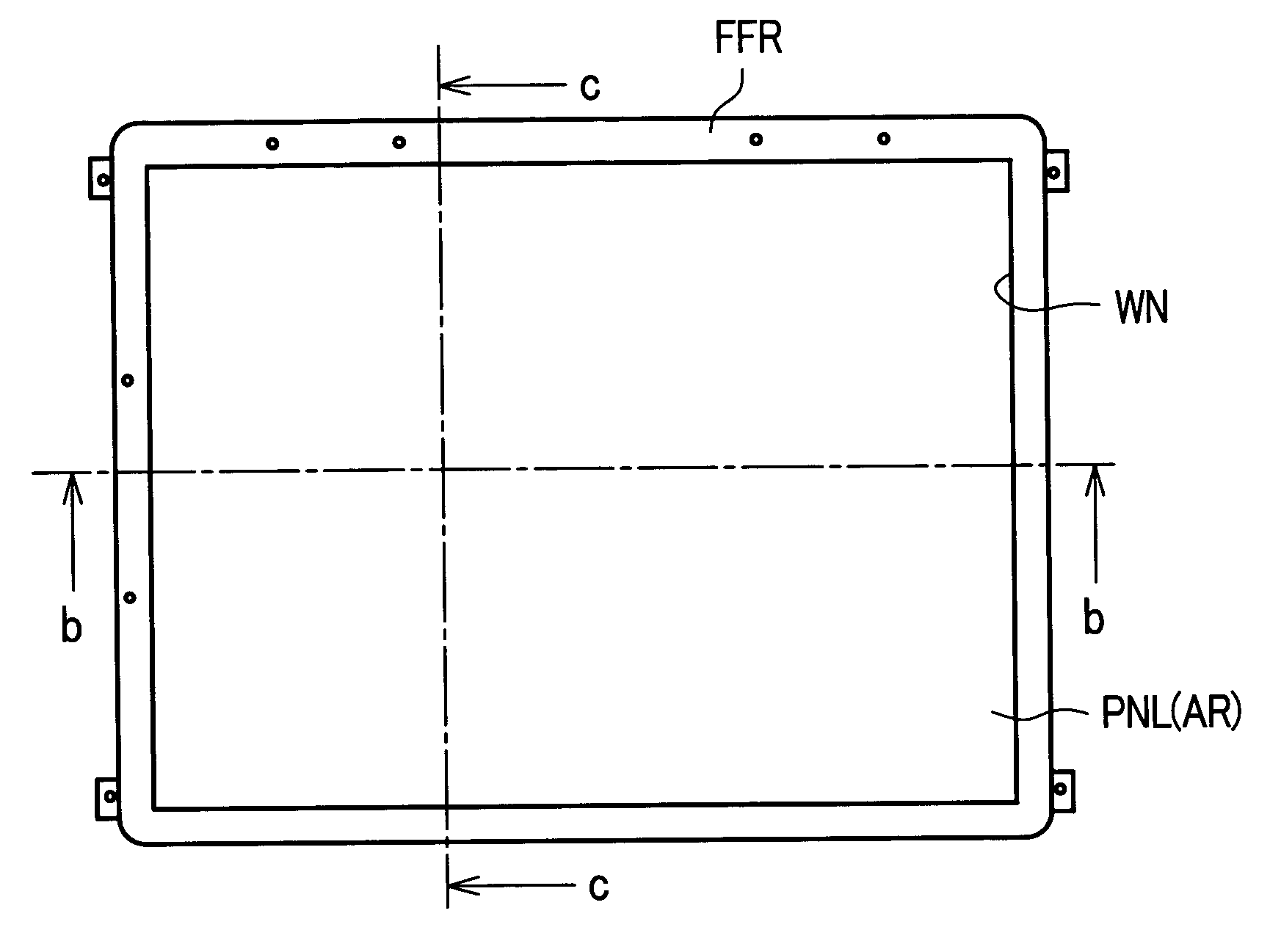
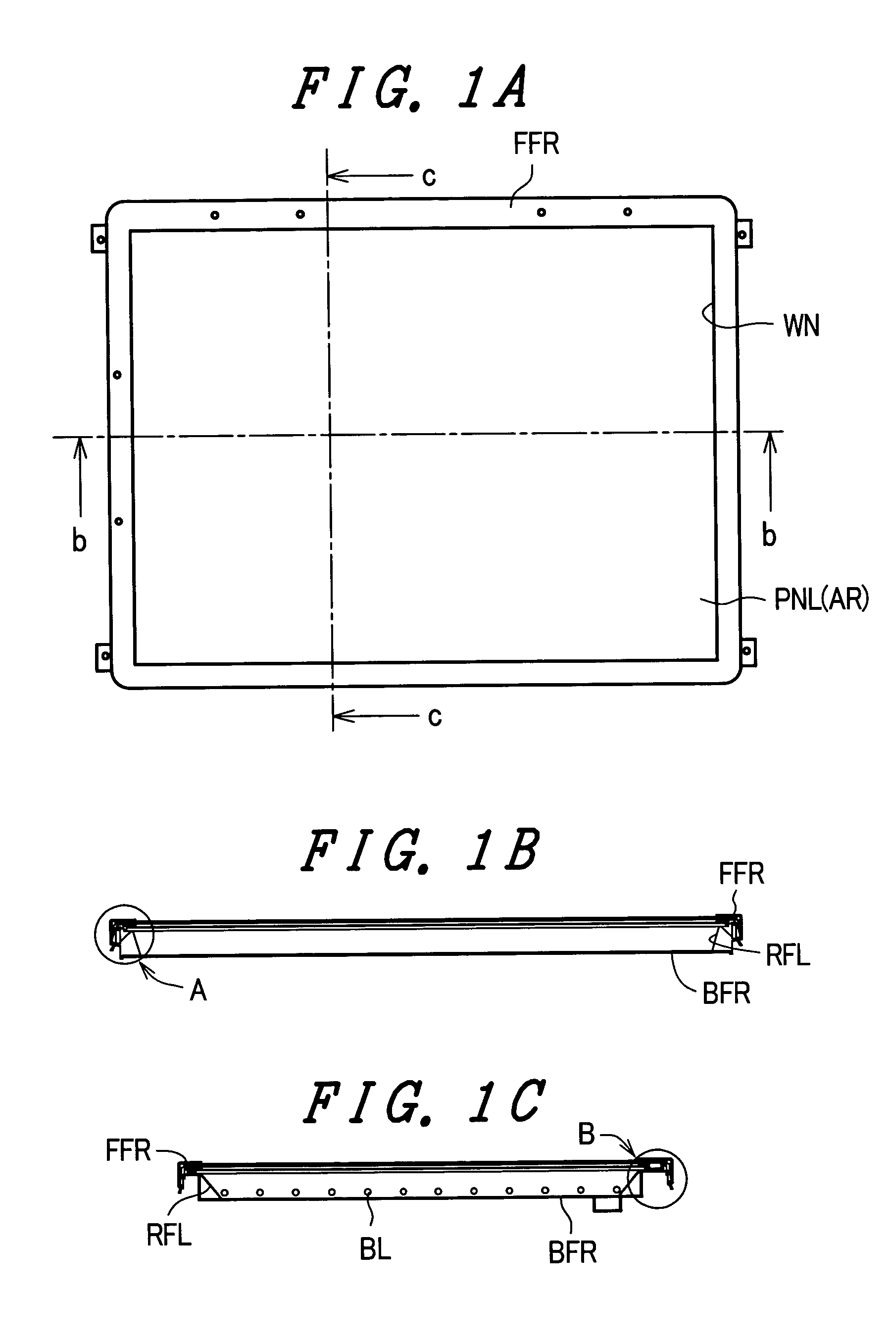
FIG. 1A is a view showing one embodiment of an image display device according to the present invention and is a front view of a liquid crystal display device formed in a module. Here, “front” means a face at a side which an observer observes an image. Further, FIG. 1B a cross-sectional view taken along a line b-b in FIG. 1A and FIG. 1C is a cross-sectional view taken along a line c-c in FIG. 1A.

In FIG. 1A, for example, there is provided an upper frame FFR which is made of metal. With respect to this upper frame FFR, a liquid crystal display part AR of a liquid crystal display panel PNL is exposed through an opening portion (window) WN formed in the upper frame FFR.

That is, the upper frame FFR covers a peripheral portion of the liquid crystal display panel PNL except for the above-mentioned liquid crystal display part AR and, at the same time, engages with a side face of a middle frame MFR described later on which the liquid crystal display panel PNL is mounted.

On a back face o...

embodiment 2

FIG. 6A is a perspective view of the lower frame BFR which is incorporated into the lower frame BFR or is constituted as a portion of the lower frame BFR. In this embodiment, the lower frame BFR is constituted as the lower frame BFR.

Lamps (for example, cold cathode ray tubes or the like) not shown in the drawings are arranged such that a sheet-like reflector described later is placed on the lower frame BFR and, thereafter, the lamps (eight lamps, for example) which extend in the x direction and are juxtaposed in the y direction at a substantially equal interval are arranged.

The lower frame BFR has respective sides thereof which are disposed parallel to the x direction in the drawing bent toward the liquid crystal display module side by 90° to ensure a mechanical strength thereof. Further, the lower frame BFR has the sides thereof further bent by 90° to form flat faces. The middle frame MFR is placed on the flat faces.

Then, in view of the necessity of arranging the sheet-like r...

embodiment 3

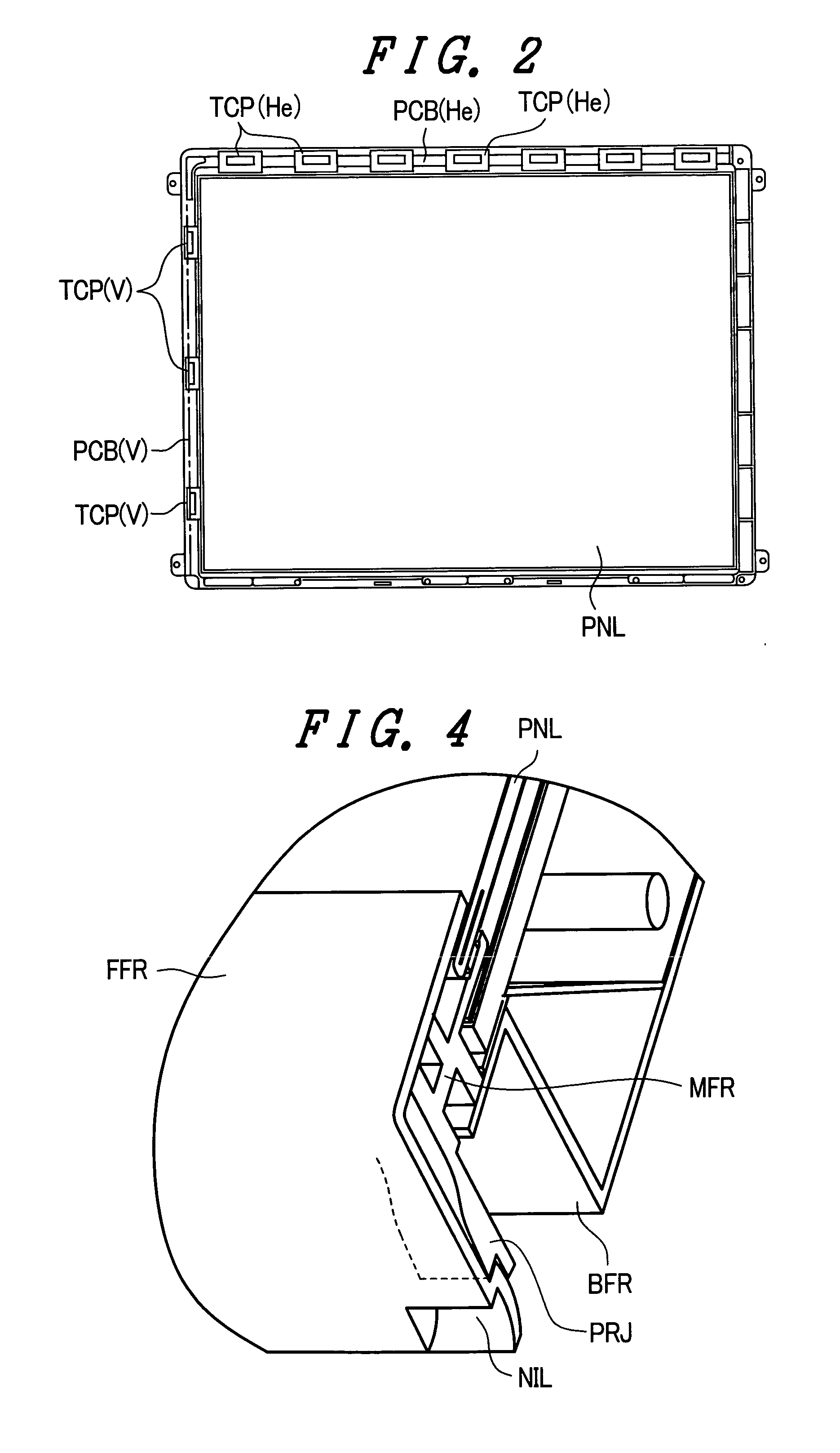
FIG. 9 is a plan view showing a state in which a liquid crystal display panel module PNLM which is placed on an upper face of the middle frame MFR is positioned using a projecting portion PRJ1 formed on the upper surface of the middle frame MFR.

The projecting portion PRJ1 is formed around the whole periphery of the liquid crystal display panel PNL such that the projecting portion PRJ1 surrounds the liquid crystal display panel PNL. The projecting portion PRJ1 is provided for preventing the intrusion of dust from the outside.

Here, since the structure which the projecting portion PRJ1 surrounds is the liquid crystal display panel PNL, the semiconductor devices TCP and the printed circuit boards PCB which are connected to the liquid crystal display panel PNL are arranged on the projecting portion PRJ1.

Further, this projecting portion PRJ1 also has a function of supporting the upper frame FFR, wherein the projecting portions PRJ1 uniformly supports the upper frame FFR so as to pre...


PUM

PropertyMeasurementUnit
angleaaaaaaaaaa
curvatureaaaaaaaaaa
angleaaaaaaaaaa

Abstract

An image display device includes a display panel module, a middle frame which places the display panel module thereon, and an upper frame which is engaged with a side face of the middle frame in a state where the upper frame covers a periphery of the display panel module, wherein the engaging portion includes projecting portions on a side face of the middle frame, each projecting portion being smoothly raised in the direction opposite to the display panel module and forming a sharp stepped portion which follows a raised portion, and pawl portions which are formed on portions of the upper frame which face the projecting portions, the pawl portions being bent along side faces of the stepped portions of the projecting portions and, thereafter, being bent such that the pawl portions extend while having arcuate face which has a center thereof in the vicinity of bent portions.

Description

BACKGROUND OF THE INVENTION 1. Field of the Invention The present invention relates to an image display device, and more particularly to an image display device which forms an image display panel and the like into a module using a frame. 2. Description of the Related Art A liquid crystal display device is, for example, configured such that a backlight unit is arranged on a back face of a liquid crystal display panel and these components are formed into a module using an upper frame, a lower frame and the like. The upper frame constitutes a frame which covers a periphery of the liquid crystal display panel while exposing a liquid crystal display part of the liquid crystal display panel and engages with the lower frame (for example, see Japanese Unexamined Patent Publication 2001-33764, FIG. 2). Further, the lower frame usually constitutes a portion of the backlight unit, wherein a plurality of fine line-shaped lamps and a reflector which reflects light from these lamps to the l...

Claims


Application Information

Patent Timeline
Patent Type & Authority Applications(United States)
IPC IPC(8): G02F1/1333G02F1/13G02F1/133G06F1/16G09F9/00
CPCG02F1/133308G02F2001/133317G06F2200/1612G06F1/1601G02F2201/465G02F1/133317
Inventor KITAKA, TAKAAKITSUBOKURA, MASAKIAZUMA, YUJI
Owner PANASONIC LIQUID CRYSTAL DISPLAY CO LTD
Why Eureka
Try Eureka