Active night vision system for vehicles employing Anti-blinding scheme

Inactive Publication Date: 2005-05-05
FORD GLOBAL TECH LLC
View PDF6 Cites 19 Cited by
  • Summary
  • Abstract
  • Description
  • Claims
  • Application Information

AI Technical Summary

Benefits of technology

[0006] The present invention provides an active night vision system and method related thereto which mitigates the blinding effects of nearby similarly equipped vehicles. The anti-blinding scheme of the present invention synchronizes the pulsed light sources of respective vehicles approaching each other from opposite directions to be out-of-phase without the use of GPS or any other external reference source. A night vision system in accordance with one embodiment of the present invention includes an illuminating device such as a NIR light source and beam-forming optics for illuminating a region in the forward direction of travel of the vehicle. A receiver, such as a camera, receives light reflected off objects in the illuminated region and generates a video signal responsive to the received light. A second light source is provided which acts as a timing trigger pulse operating at a wavelength differen

Problems solved by technology

Mid-infrared night vision systems have relatively few pixels and, accordingly, images formed using such cameras have low video resolution and a relative

Method used


Image

  • Active night vision system for vehicles employing Anti-blinding scheme
  • Active night vision system for vehicles employing Anti-blinding scheme
  • Active night vision system for vehicles employing Anti-blinding scheme

Examples


Example

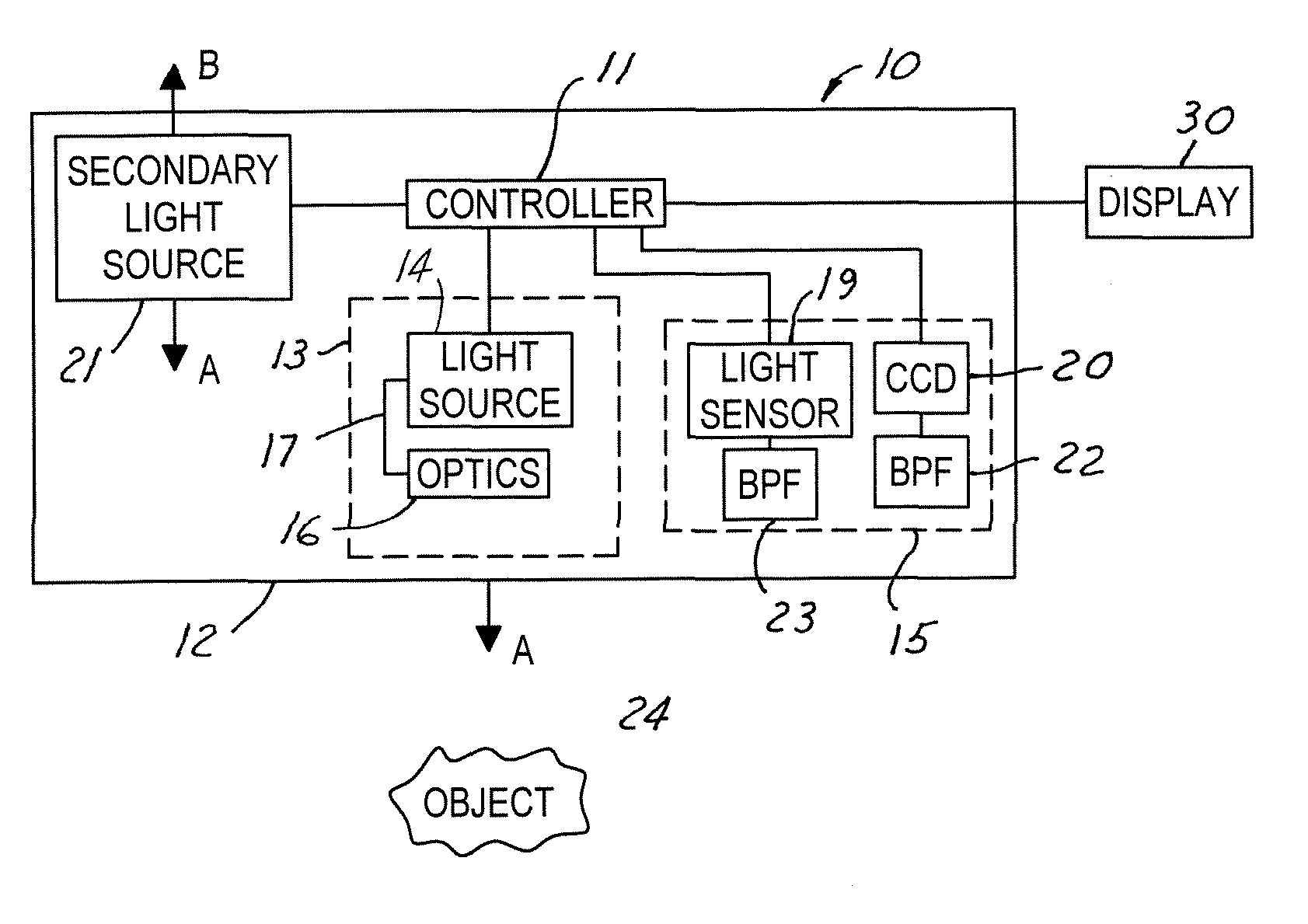
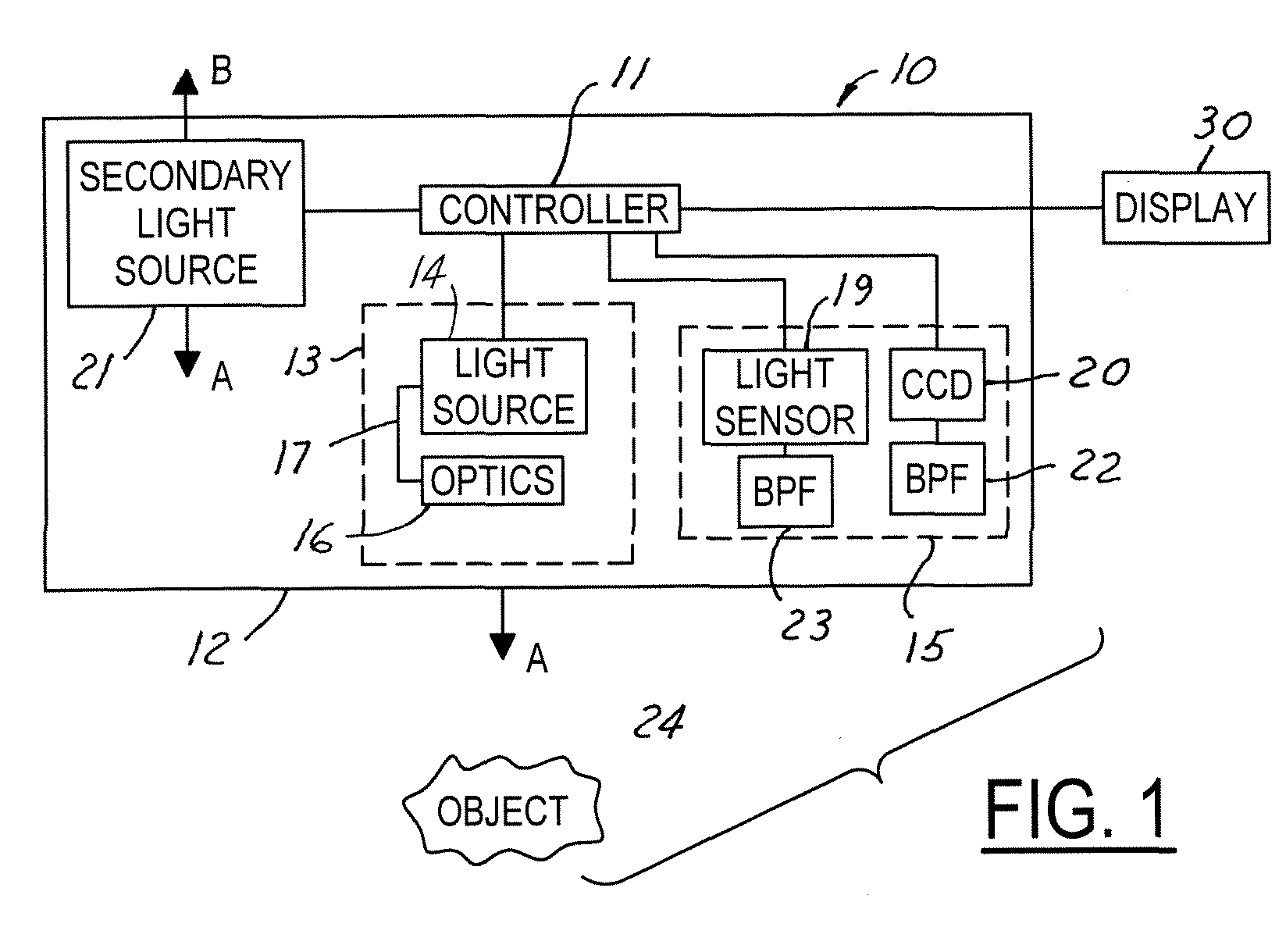
[0021] Referring now to the drawings wherein like reference numerals are used to identify identical components in the various views, FIG. 1 illustrates a night vision system 10 for detecting objects at relatively low visibility light levels. The system 10 may be utilized in a plurality of applications. For example, the system 10 may be used in an automotive vehicle to allow a driver to see objects at night that would not otherwise visible to the naked eye. As illustrated, the system 10 includes a controller 11, an illumination subsystem 13, a receiver 15 and, a secondary light source 21.

[0022] Several of the system components may be included within a housing 12. It should be understood, however, that the components of system 10 contained within housing 12 could be disposed at different locations within the vehicle wherein the housing 12 may not be needed. For example, the components of the system 10 could be disposed at different operative locations in the automotive vehicle such t...


PUM


Abstract

A night vision system for a vehicle includes a pulsed light source for illuminating a region proximate the vehicle and a secondary trigger light source operating at a predetermined pulse timing and second wavelength. A light sensor detects light at the second wavelength. The trigger light pulses are used to indicate the pulse timing of each respective vehicle's primary NIR light source. Upon detecting another vehicle's trigger light source, the controller adjusts the pulse phase of the first light source to be exactly out-of-phase with that of the oncoming vehicle since the pulsed timing of the oncoming vehicle's NIR light source is known upon detection of the opposing vehicle's trigger light source. Each vehicle can then adjust its primary light source to be out-of-phase with the other vehicle and, hence, non-interfering.

Description

BACKGROUND OF INVENTION [0001] The present invention relates to a night vision system for detecting objects at relatively low visible light levels. In particular, the invention concerns an active night vision system having an anti-blinding scheme employing pulsed illumination and synchronization with detected pulsed light sources from oncoming vehicles. [0002] Night vision systems are utilized to allow a user to see objects at relatively low visibility light levels. Night vision systems typically are classified as either passive night vision systems or active night vision systems. In known passive night vision systems used in automotive applications, mid-infrared cameras are used to image objects using the ambient infrared light emitted by the objects in the environment. Mid-infrared night vision systems have relatively few pixels and, accordingly, images formed using such cameras have low video resolution and a relatively narrow field of view. Known active night vision systems util...

Claims


Application Information

Patent Timeline
IPC IPC(8): G01S17/89F21V11/00G01S17/18H01J40/14H04N7/18
CPCG01S17/107H04N7/188G01S17/89G01S17/18
Inventor STEPHAN, CRAIG H.REMILLARD, JEFFREY T.
Owner FORD GLOBAL TECH LLC
Why Eureka
Try Eureka