Touch sensing circuit and method thereof

Active Publication Date: 2015-09-17
ILI TECHNOLOGY CORPORATION
View PDF2 Cites 3 Cited by
  • Summary
  • Abstract
  • Description
  • Claims
  • Application Information

AI Technical Summary

Benefits of technology

[0009]The invention is directed to a touch sensing circuit and a touch sensing method f

Problems solved by technology

In practice, a detection result of a touch panel may be incorrect due to the interference of external signals.
For example, a c

Method used


Image

  • Touch sensing circuit and method thereof
  • Touch sensing circuit and method thereof
  • Touch sensing circuit and method thereof

Examples


Example

[0027]Technical terms of the application are based on the general definition in the technical field of the application. If the application describes or explains one or some terms, definitions of the terms are based on the description or explanation of the application.

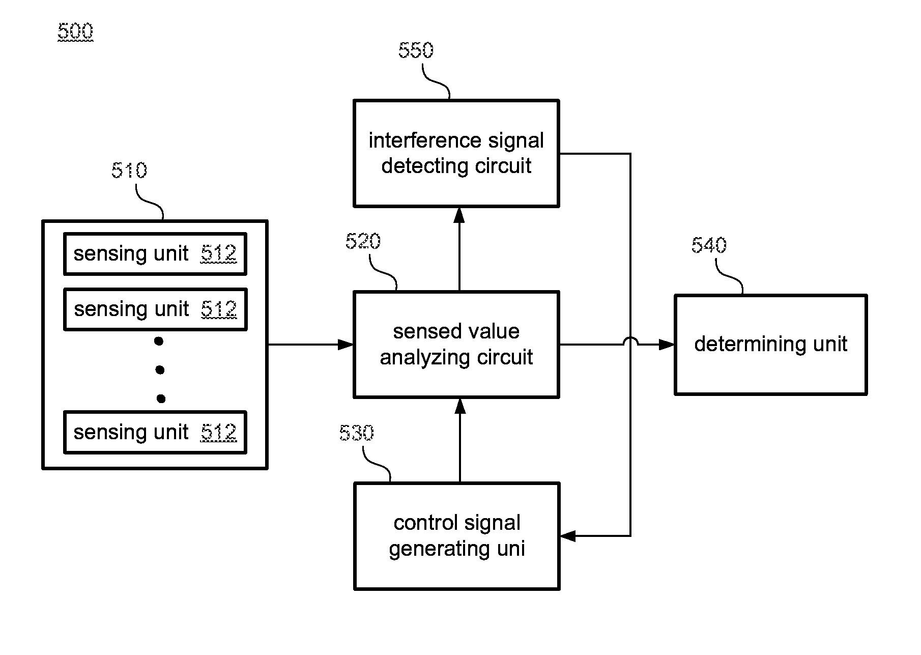
[0028]The present invention discloses a touch sensing circuit and a touch sensing method capable of detecting an interference signal to mitigate an effect of the interference signal on the touch control sensitivity. The touch sensing circuit and the touch sensing method are applicable to capacitive touch panels. In possible implementation, one skilled person in the art may choose equivalent devices or steps to implement the disclosure based on the disclosure of the application. That is, the implementation of the disclosure is not limited in the embodiments disclosed in the disclosure. Further, a part of the elements included in the touch sensing circuit of the disclosure may be individually known. Without affecting the ...


PUM


Abstract

A touch sensing circuit is applied to a touch panel to generate a sensing signal. The touch panel includes a sensing device. The touch sensing circuit includes: an interference signal detecting circuit, configured to detect an interference signal of the touch panel to generate an interference signal detection result; a control signal generating unit, configured to generate a control signal according to the interference signal detection result; and a sensed value analyzing circuit, configured to charge the sensing device in a first time interval and to discharge the sensing device in a second time interval, and to generate the sensing signal according to a sensed value of the sensing device. A length of one of the first time interval and the second time interval changes according to a control signal.

Description

[0001]This application claims the benefit of Taiwan application Serial No. 103109345, filed Mar. 14, 2014, the subject matter of which is incorporated herein by reference.BACKGROUND OF THE INVENTION[0002]1. Field of the Invention[0003]The invention relates in general to a touch sensing circuit, and more particularly to a touch sensing circuit and method capable of detecting an interference signal and adjusting charging and detection periods of the sensing circuit according to a detection result to enhance the sensing accuracy.[0004]2. Description of the Related Art[0005]FIG. 1 shows a function block of a conventional touch sensing circuit 100. The touch sensing circuit 100 includes a sensing device, a sensed value analyzing circuit 120, a control signal generating circuit 130 and a determining unit 140. For a capacitive touch panel, many transparent electrodes are disposed below a surface glass cover layer, and capacitance devices are equivalently formed between the transparent elec...

Claims


Application Information

Patent Timeline
IPC IPC(8): G06F3/044
CPCG06F3/044G06F3/04166G06F3/0418
Inventor HUNG, GUO-KIANGCHEN, CHIH-YINGPAN, HSUAN-I
Owner ILI TECHNOLOGY CORPORATION
Why Eureka
Try Eureka